Configuring I/O
You can configure the router’s General Purpose Input/Output (GPIO) pins in AirLink OS. The pins can be used to turn switches on and off, or report data such as temperatures, pressures and flow rates.
This router model has one I/O pin available for analog input or digital input/output configuration:
- Power connector—Pin 4 (GPIO)

You can use Pin 4 in conjunction with Telemetry to configure the router to send a report when the I/O pin state changes; for example when a switch is opened or closed. The digital input can also be used with the standby timer. For more information, refer to the Hardware Guide for the router.
 Initializing Table Of Contents...
Configuration
To set the mode for the I/O pin:
Go to System > I/O > Configuration.
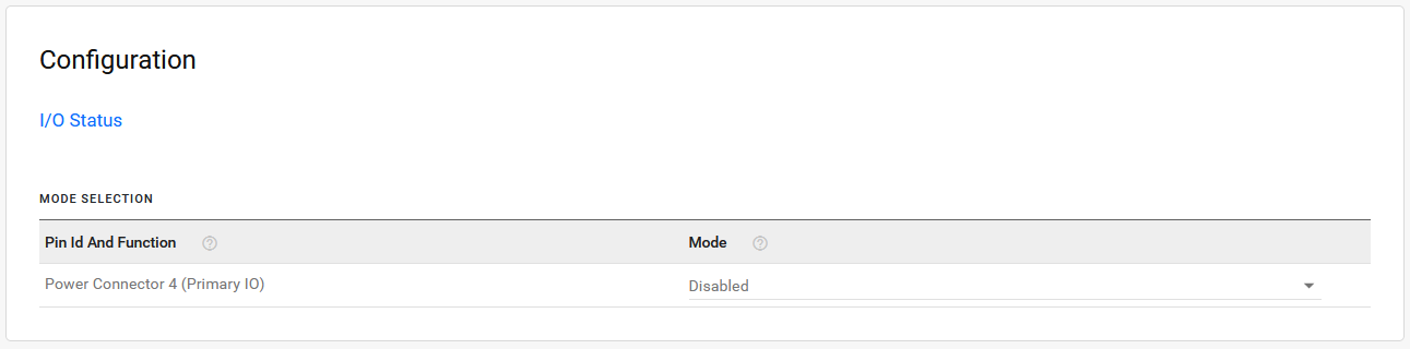
Select the Mode. The mode settings available are:
- Digital Input and Output
- Analog Input
- Disabled (default)
Once the Mode is selected, a corresponding entry will appear in the Analog Inputs table or the Digital Inputs and Digital Outputs tables.

Analog Inputs
Analog inputs monitor a voltage range in small increments. This allows you to monitor equipment that reports status as an analog voltage. Examples include:
- Power supply voltage
- Temperature, weight, volume, flow represented as voltage
- An incremental gauge with a voltage output
- Vehicle battery voltage

In the Analog Inputs Table you can transform the voltage readings to a more convenient unit of measurement. For example, degrees Celsius or Fahrenheit for temperature, liters for volume, etc.
- Deadband: the minimum change in mV since the last analog I/O value was received that is needed to update the value again.
- Coefficient: a multiplicative value used in calculating the Transformed Value (displayed in Status > System > I/O)
- Offset: a value used to compensate the Transformed Value (displayed in Status > System > I/O)
- Unit (optional): Enter the unit of measurement for the transformed analog value. For example, mV, V, degrees Celsius, kg, L, %, and so on. This entry does not affect any calculations, but it is shown with the Transformed Value in the I/O Status table.
Step 1: Coefficient and Offset
Before you configure, you need to locate or calculate the coefficient and the offset values.
Consult the user documentation for the equipment you want to monitor. It should provide you with the coefficient to convert volts to the appropriate unit of measurement and the offset value (the difference between the equivalent value for 0 volts and 0), or provide information on equivalent values for voltage readings from which you can calculate the coefficient and offset. (If this information is not available in the user documentation, contact the manufacturer.)
For example, if the equipment monitors temperature, and has a scale from 0 volts to 30 volts, the equipment specifications should provide information similar to the following:
0 V is equivalent to –20°C
30 V is equivalent to 100°C
This is expressed algebraically as follows:
a * 0V + b = –20C
a * 30V + b = 100C
where:
a = coefficient
b = offset
For this example, you can calculate a as follows:
(a * 30V + b) – (a * 0V + b) = 100C – (–20)
a * 30V = 120V
a = 4
To calculate b, substitute a into the first equation above:
4 * 0V + b = –20
b = –20
Step 2: Configure AirLink OS
For each of the analog inputs you want to configure:
Go to System > I/O > Analog Inputs.
Enter the values for the coefficient and offset. (In this example, the coefficient is 4 and the offset is –20.)
AirLink OS will show the value of the transformed analog input.
Digital Inputs
Digital inputs monitor contact closures on a switch. This allows you to monitor changes such as:
- When a door or latch is open or closed
- When a container is full or empty
- When a switch or valve is opened or closed
- The level of fuel in a vehicle (connected to an on/off sensor)
- When the trunk of a vehicle is opened or closed
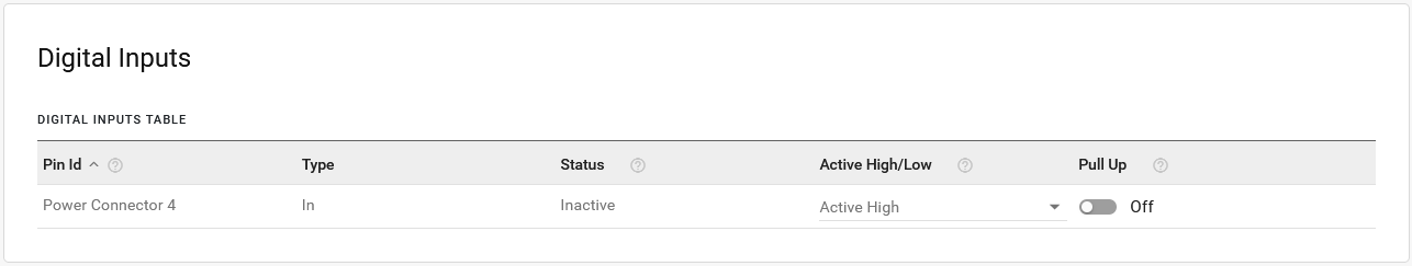

The Digital Inputs Table displays:
- Type: Disabled or In (input)
- Status: Inactive (false) or Active (true)
- Active High/Low: options are Active High, Active Low
- Pull Up: options for the pull-up resistor are On or Off. In some applications, enabling Pull Up ensures that an Active High or Low logic level persists after the digital input signal is received, thus preventing a circuit from floating.
Configure Digital Input
For each of the digital inputs you want to configure:
Go to System > I/O > Digital Inputs.
In the DIGITAL INPUTS TABLE, select Active High or Active Low.
Enable/disable the Pull Up.
The power connector GPIO (pin 4) digital input can also be used to put the device into a standby mode and to wake the router up. To configure this, see Configuring Power Settings .
Digital Outputs
When Power Connector pin 4 is configured as Digital Input and Output, you can configure the Digital Outputs settings. You can use Digital Output to drive a relay or for other uses where a switchable low-side current sink is required.
Configure Digital Output
To enable Digital Output:
Go to System > I/O > Digital Outputs.
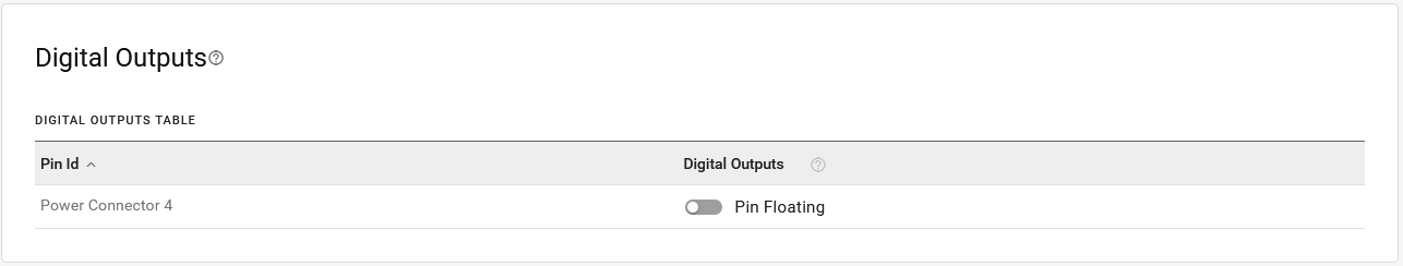
In the DIGITAL OUTPUTS TABLE, set Digital Outputs to Pin Grounded.

I/O Status
To view the status of the router’s GPIOs, go to Status > System > I/O (or click the link under Configuration).


The I/O STATUS table shows each enabled I/O Pin and its:
- Configured Mode
- Raw Value: voltages in mV for Analog Input or 0/1 for Digital Input/Output
- Transformed Value: calculated as (Value in units of Volts * Coefficient) + Offset. Allows for conversion of the analog I/O value to meaningful ranges/values where the Transformed Value can then be used in the chosen events reporting output.
The transformation function uses Raw Value in units of volts, not millivolts, to display the Transformed Value.
Data sampling is taken over 20 measurements during a 250 ms interval. The measurements are averaged to generate a sample. If the sample has changed by the amount of the Deadband or a time period of 2.5 minutes has passed, then the Raw Value is updated.
GPIO Reporting
If you want to add GPIO state to reports, you can do so in a custom report. See Services > Telemetry > Custom Reports.