Configuring GNSS and Location Reports
XR Series routers are equipped with location tracking, enabling you to track the movements of a vehicle or other devices that move. This section describes how the router relays location information as well as other data for use with tracking applications.
Common uses for location reporting include:
- Driver navigation: The router provides real-time location data via the serial or Ethernet port to a local application, including applications that provide mapping and navigation support.
- Computer-Aided Dispatch/Automatic Vehicle Location (CAD/AVL): The router provides real-time location data to a server that tracks the location and other variables of the vehicle or asset.
For instructions on configuring the router for Advanced Mobility Reporting (AMR) (available in ALMS), see this page.
 Initializing Table Of Contents...
Supported Location Report Protocols
National Marine Electronics Association (NMEA®): NMEA is an ASCII protocol used by many location tracking applications.
Trimble® ASCII Interface Protocol (TAIP): TAIP is a digital communication interface based on printable ASCII characters over a serial data link.
Hardware Requirements
Ensure that a GNSS antenna is connected to the dark blue FAKRA connector on the router. See the XR Series Hardware Guide for installation and antenna connection instructions. For compatible antennas sold by Sierra Wireless, see our website.
After starting up the router, check the GNSS LED to confirm GNSS operation. The GNSS LED will be red while searching for a fix. After getting a fix, it is yellow (Dead Reckoning is enabled but not calibrated) or green (Dead Reckoning is calibrated or disabled). Dead Reckoning enhances vehicle tracking when satellite GNSS service is impeded or unreliable.
See this page for full LED information.
Our GNSS solution can use signalling from up to four constellations to provide a more reliable and accurate location fix. For legacy applications that may require GPS-only, you can limit the location service by selecting the “GPS Only” option. See LOCATION CONSTELLATION below.
Enabling Location
Under Services > Location > General, ensure that GNSS ENABLE is On.

GNSS is enabled by default, and begins working when the router is powered on with a GNSS antenna connected. GNSS status is reported under GNSS STATE, and can include the following status messages:
- Starting
- Device Unavailable
- Waiting For New Fix
- Location Fix Acquired
- Firmware Upgrade in Progress
- Firmware Upgrade Failed
- Firmware Upgrade Successful
Status messages related to Firmware are shown after you enable or disable DEAD RECKONING, which changes the GNSS Firmware that the router uses. See DEAD RECKONING below.
For fine tuning GNSS, you can configure the settings listed below:
| SETTING | DESCRIPTION | RANGE | DEFAULT |
|---|---|---|---|
| GNSS CURRENT FIRMWARE | Current version of firmware on the router’s GNSS (Global Navigation Satellite System) module | n/a | n/a |
| DEAD RECKONING |
Enables or disables Dead Reckoning. After you change the Dead Reckoning setting, the router switches to a different GNSS firmware that supports or does not support Dead Reckoning. Check the GNSS STATE to monitor the progress of the firmware switch. Dead Reckoning operates alongside satellite (GNSS) navigation to help maintain location tracking capability when a GNSS signal is impaired or temporarily unavailable. For more information see About Dead Reckoning below. |
On, Off | On |
| MAXIMUM VEHICLE SPEED (KM/H) | This setting helps to filter out erroneous location fixes by setting an expectation of the vehicle’s maximum achievable speed. | 0—1000 | 250 KM/H |
| LOCATION CONSTELLATION | Location constellation (satellite group) you want the router to use |
|
GNSS (GPS, Galileo, QZSS, GLONASS) |
| IGNITION PARK MODE |
You can configure how GNSS location fixes are reported when Ignition is off. The setting can remedy Location Fixes drifting when vehicles are parked and are in Dead Reckoning mode.

|
|
Non-DR Location Fixes |
| GNSS ANTENNA BIAS | Optimize the router for the type of connected GNSS antenna |
On (required for active GNSS antenna) Off (compatible only for passive GNSS antenna) |
On |
| GNSS ANTENNA DETECTION | Enable/Disable the reporting of GNSS Antenna State under Status/Monitoring > Status > Location. When disabled, GNSS Antenna State is reported as Not available. | Off, On | Off |
| NMEA LOGGING | You can enable NMEA LOGGING to have the router log NMEA sentences to temporary files (lost upon reboot). The logging can hold up to the last 24 hours of NMEA sentences. You can enable NMEA LOGGING to download NMEA logs from the router. After collecting the raw NMEA data, you can save it by generating and downloading a Troubleshooting package under System > Logs > Troubleshooting Package. | Off, On | Off |
Configuring Location Reports
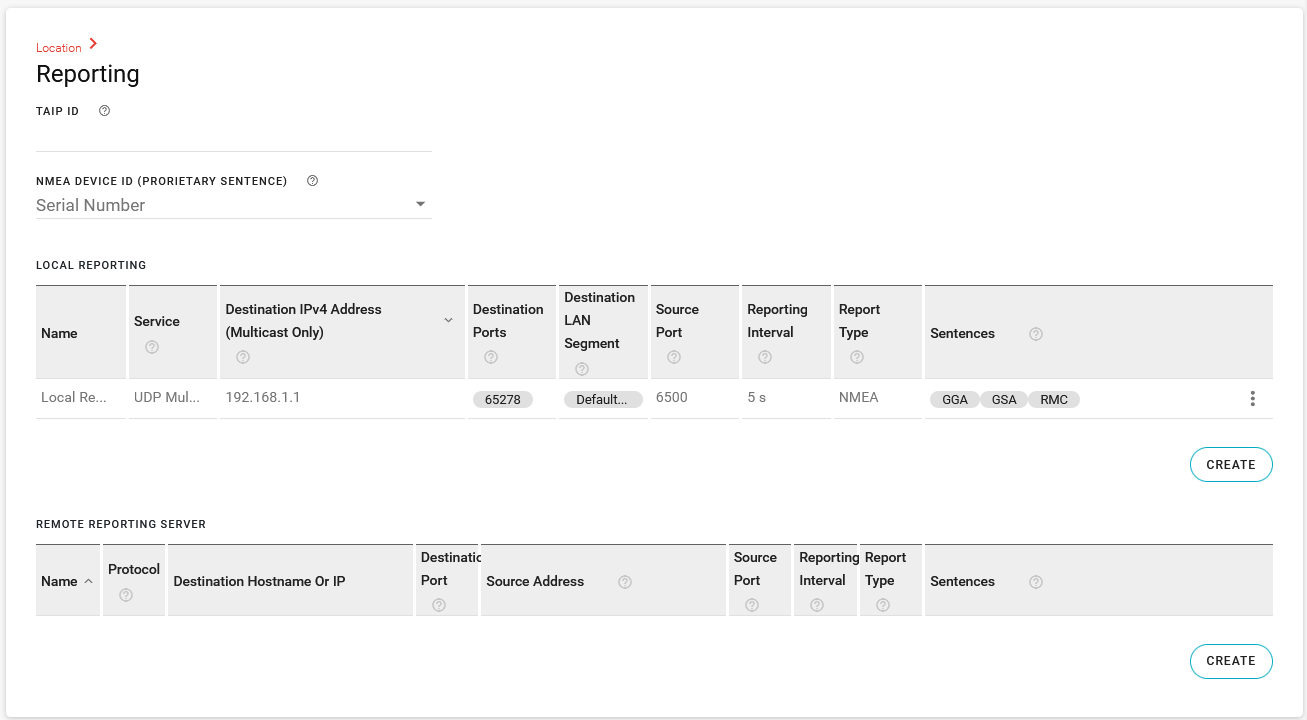
Under Location > Reporting:
- Enter the TAIP ID (used for TAIP reports; not required for NMEA). This can be any four-character alphanumeric string as per the TAIP standard.
- Select the NMEA DEVICE ID (PROPRIETARY SENTENCE), which is used in NMEA reports to identify a router or vehicle. This can be the router Serial Number or select Custom ID to enter your own ID string from 1 to 50 characters.

Local Reporting
Local reports are sent via UDP to an IP address on the LAN. To configure Local Reporting, click CREATE below the LOCAL REPORTING table. In the Create Local Reporting window, configure the following settings:

| SETTING | DESCRIPTION | RANGE | DEFAULT |
|---|---|---|---|
| NAME | Enter a name for the report. | n/a | n/a |
| SERVICE | The protocol over which reporting traffic is sent. UDP Broadcast sends traffic to a subnet, while UDP Multicast sends traffic to a LAN or another network. When UDP Multicast is selected, you must enter a Destination IPv4 address. | UDP Broadcast or UDP Multicast | UDP Broadcast |
| DESTINATION IPV4 ADDRESS (MULTICAST ONLY) | This setting is available when UDP Multicast service is selected. To send the location report(s) to a local LAN client, enter the address here. If there is more than one local client, it is advisable to set up a DHCP reservation or set a static IP address on the client. | n/a | n/a |
| DESTINATION PORTS | Enter the port(s) on which the CAD/AVL application is configured to receive data. The port number(s) should be available from your CAD/AVL administrator or application documentation. | 1–65535 | 65278 |
| DESTINATION LAN SEGMENT |
Enter the LAN segment for multiple clients. If you have multiple clients that require the location reports, you can send reports to each client on a particular LAN segment. If you need to send reports to multiple LAN segments, each LAN segment needs to be included in a separate Local Report. |
n/a | n/a |
| SOURCE PORT | If you require the ability to control the UDP source port for sending local location reports, enter a port number. In some cases, the SOURCE PORT and DESTINATION PORT may need to match. The setting is blank by default. If blank, the router selects a random source port. | 1–65535 | Blank |
| REPORTING INTERVAL | Sets how frequently the location report is sent to the LAN or IPv4 destination. | 1–100000 seconds | 5 |
| REPORT TYPE |
Select the report type (or protocol, as described above).
|
|
NMEA |
| SENTENCES |
If the report type is NMEA, you can select the desired combination of GGA, GSA, RMC, VTG, and GSV sentences, along with the Proprietary Device ID. Some typical sentences are below.
|
GGA, GSA, RMC, VTG, GSV, Proprietary Device ID | GGA, GSA, RMC |
Remote Reporting
To configure the Remote Reporting Server, click CREATE below the REMOTE REPORTING SERVER table. In the Create Remote Reporting Server window, configure the following settings:

| SETTING | DESCRIPTION | RANGE | DEFAULT |
|---|---|---|---|
| NAME | Enter a name for the reporting server configuration. | n/a | n/a |
| PROTOCOL | Select the protocol over which remote reporting traffic will be sent. | TCP, UDP | UDP |
| DESTINATION HOSTNAME OR IP |
IP address or FQDN (fully qualified domain name) of the server where location reports are sent. Example: 192.100.100.100. The IP address can be for a local host or a remote server that is accessed over-the-air or via a VPN tunnel. If an IP with the last octet of 255 is configured (i.e. 192.168.13.255), a report would be broadcast to all IPs on that subnet. When configured to a local host subnet, any connected device would receive the report. |
n/a | n/a |
| DESTINATION PORT | Destination port on the server where location reports are sent. The destination port can be the same for all servers or you can configure a different destination port for each server. | 1–65535 | 22335 |
| SOURCE ADDRESS | Enter a source address. The IP address has to match that of a configured LAN segment. If passed through a VPN, the router’s “default-LAN” IP address will be used by default. If NOT passed through a VPN, the router’s WAN IP address will be used instead. If left blank, the SOURCE ADDRESS is the IP address of the Default-LAN. | IPv4 or IPv6 address | Blank |
| SOURCE PORT | If you require the ability to control the UDP/TCP source port for sending location reports, enter a port number. In some cases, the SOURCE PORT and DESTINATION PORT may need to match. | 1–65535 | 22335 |
| REPORTING INTERVAL | Sets how frequently the location report is sent to the IPv4 destination. | 1–100000 seconds | 5 |
| REPORT TYPE |
Select the report type (or protocol, as described above).
|
|
NMEA |
| SENTENCES |
If the report type is NMEA, you can select the desired combination of GGA, GSA, RMC, VTG, and GSV sentences, along with the Proprietary Device ID. Some typical sentences are below.
|
GGA, GSA, RMC, VTG, GSV, Proprietary Device ID | GGA, GSA, RMC |
Forwarding Local Reports to the Serial Port
It is possible to send reports via the RJ45 Serial port on the router using the default destination local IP address (192.168.1.1) and then setting the Serial port in PAD mode to listen and forward to the serial port. This configuration is useful in cases where local serial forwarding is used for sending reports to laptops in docking stations in a service vehicle.
The destination local IP address can be modified from default, so it should be checked under Networking > Zones settings > LAN Segments.
To configure sending local reports to the Serial Port:
Under Location > Reporting > LOCAL REPORTING, configure Local Reporting for UDP Multicast using the destination local IP address, for example 192.168.1.1.
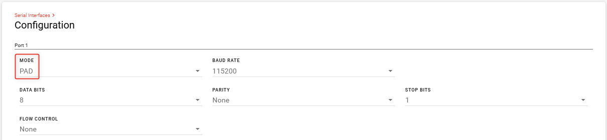
Go to Hardware Interfaces.
Under Serial Interfaces > Configuration, set the MODE for Port 1 to PAD.
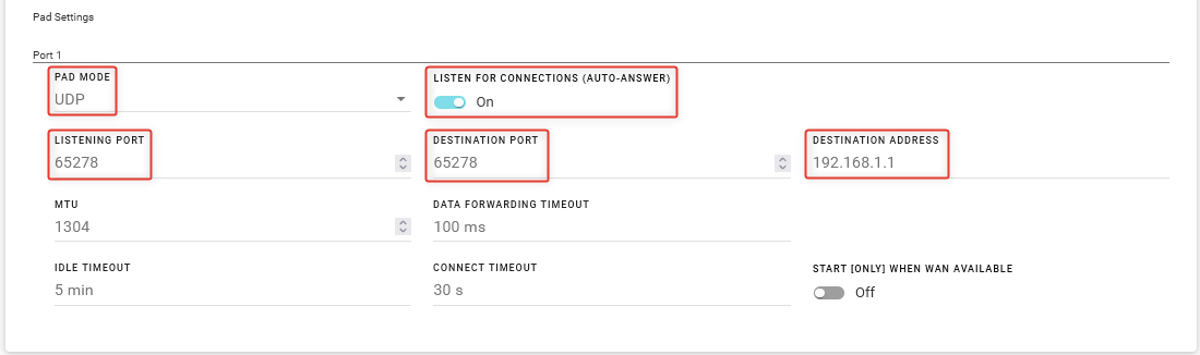
Under PAD Settings, configure Port 1 as follows:
- PAD MODE: UDP
- LISTEN FOR CONNECTIONS (AUTO-ANSWER): On
- LISTENING PORT and DESTINATION PORT: Same port configured in Step 1
- DESTINATION ADDRESS: Same Destination IP Address used in Step 1. For example, 192.168.1.1.
The receiving application may have additional requirements for reducing the BAUD rate or configuring other flow control parameters. Consult the documentation from the application vendor for details.
Click SAVE.
To confirm operation, open the CAD/AVL listening application on your computer and confirm that messages are being received and understood.


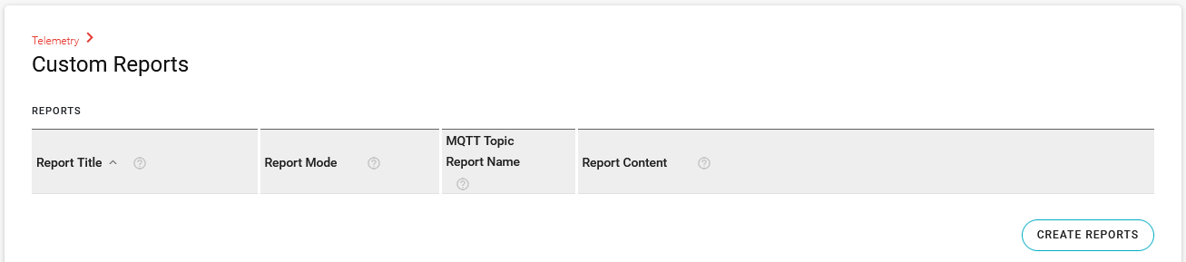
Sending GPIO State Information
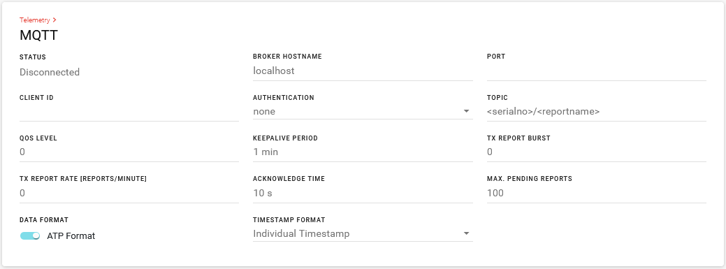
You can send GPIO status along with device location to an MQTT server using the Telemetry reporting feature, under Telemetry > Custom Reports.
There are no default GPIO reports.
To create a report to send GPIO and location information to an MQTT server:
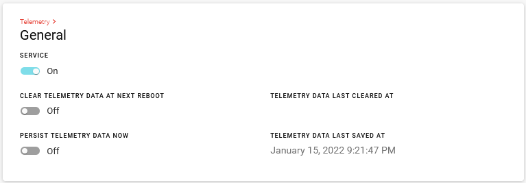
Go to Telemetry > General, turn on SERVICE.
Go to Telemetry > Custom Reports and click CREATE REPORTS.
In the Create Reports window, enter the following settings:
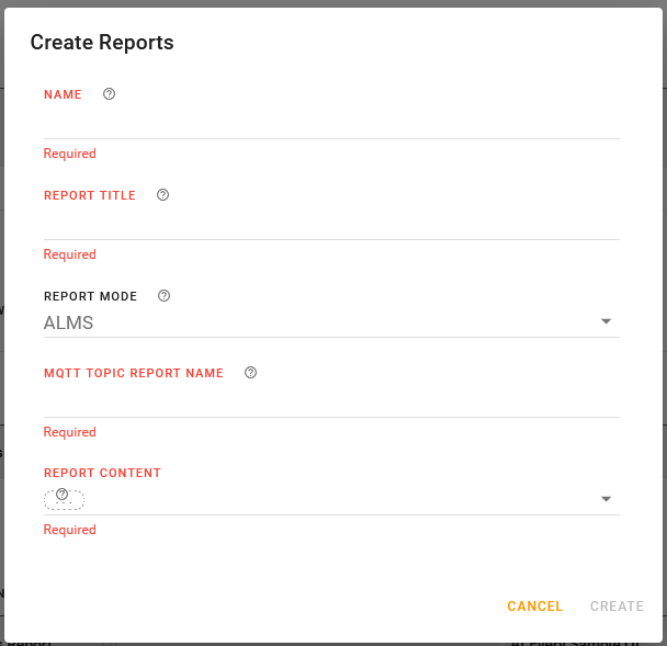
- NAME: enter a report name.
- REPORT TITLE: enter a report TITLE.
- REPORT MODE: select one of the MQTT options: MQTT or ALMS and MQTT.
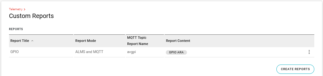
- MQTT TOPIC REPORT NAME: enter a report name. In the below image, the report is named avgpi (AirVantage General Purpose Inputs).
- REPORT CONTENT: select GPIO ARA from the list. GPIO ARA consists of the following data points:
- atp.glon: GPS longitude (decimal degrees)
- atp.glat: GPS Latitude (decimal degrees)
- atp.ghed: GPS Heading (decimal degrees)
- atp.gpi: GPIO Input Cumulative, which is a binary report of all five GPIO data points:
- Primary GPIO Input (on power connector) 0th bit: atp.pgpio
- GPIO Input 2 bit position 1: atp.gpio2
- GPIO Input 3 bit position 2: atp.gpio3
- GPIO Input 4 bit position 3: atp.gpio4
- GPIO Input 5 bit position 4: atp.gpio5
Example: GPIO Input Cumulative is calculated as follows:- Primary GPIO Input: true
- GPIO Input 2: true
- GPIO Input 3: false
- GPIO Input 4: true
- GPIO Input 5: false
Therefore GPIOInputCumulative is 01011 which equals hexadecimal 0x0B which equals decimal 11.
Click CREATE.
To generate a report on state change of the GPIO input, go to UNCONDITIONAL TRIGGERS and click CREATE UNCONDITIONAL TRIGGERS.
In the Create Unconditional Triggers window, enter the following settings:
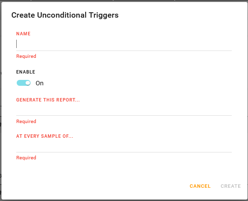
- NAME: Enter a trigger name
- ENABLE: Enable the trigger
- GENERATE THIS REPORT…: Select the GPIO report
- AT EVERY SAMPLE OF…: Select GPIO Input Cumulative
Click CREATE.
Under Telemetry > MQTT, configure the connection to your MQTT server.


About Dead Reckoning
Dead Reckoning is a feature that operates alongside satellite (GNSS) navigation to help maintain location tracking capability when a GNSS signal is impaired or temporarily unavailable. When the feature is enabled, Dead Reckoning uses the router’s built-in inertial sensors to calculate vehicle position and to continue providing location reports to ALMS and other external applications. The router uses its last known GNSS position along with sensor input to calculate vehicle position. For example, when the vehicle enters a tunnel, parking garage, or urban canyon, Dead Reckoning data augments data from the impaired GNSS signal and helps maintain accurate location reporting.
Enabling Dead Reckoning
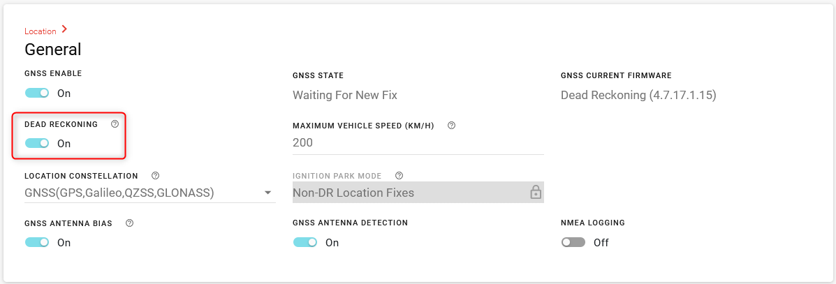
Under Services > Location > General, confirm that DEAD RECKONING is enabled. This setting ensures that Dead Reckoning GNSS firmware is running on the router, and that the router is sending dead reckoning data, as reported by the router’s inertial sensors.
If DEAD RECKONING is set to Off:
- Go to Location > General > DEAD RECKONING and click the “Off” switch, changing it to “On”.
Click SAVE.
The router switches to using a different GNSS firmware, as reported under GNSS STATE “Firmware Upgrade in Progress”. The status will change to “Waiting For New Fix” and then “Location Fix Acquired”.

Dead Reckoning can operate in one of two modes, depending on how the router is configured and connected to the vehicle.
- Tethered to the vehicle (recommended)—In this mode, the router’s Aux I/O port is connected to OBD-II/J1939 for vehicle speed input, and Vehicle Telemetry Data Collection is enabled. This mode provides a longer, more accurate location fix than Dead Reckoning without an OBD-II/J1939 connection.
- Untethered—In this mode, the router is not connected to OBD-II/J1939. Dead reckoning relies only on the router’s inertial sensors to determine vehicle location.
Sensor Calibration
When first installed in a vehicle, the router’s GNSS module needs to learn the orientation of the inertial sensors. During this calibration phase, calibration is done most efficiently when the vehicle travels with regular changes in velocity and heading while under good satellite coverage that gives high-confidence location fixes. Driving in an open, flat area with a clear view of the sky is ideal. Driving in traffic may extend the duration of the calibration process. The GNSS module keeps tuning its initial guess of inertial sensor orientation until the movement it calculates from the sensor readings is a good match against the movement derived from satellite fixes. This is why it is desirable to have speed changes and heading changes during the calibration phase, along with good satellite visibility to get high-confidence location fixes as reference during calibration.
Under these conditions, you can expect the sensors to calibrate in about 15 minutes.
In summary, for optimal calibration, the vehicle should:
- be driven in open-sky conditions
- undergo several turns at “normal” speed (over 30 kmh/20 mph)—left, right, U-turns, circles. Gradual turns, such as lane changes or driving along curves in the road, do not help with calibration.
- stop and start several times in a straight line, in the same manner that you would brake and accelerate away from stop signs, for example.
Pure Dead Reckoning Operation
When out of satellite coverage (such as while driving into an underground parking lot) the GNSS module is no longer able to fine tune for changes in inertial sensor signal levels because there are no longer reference satellite location fixes to adjust against. As a result, the accuracy of the calculations based on sensor data will degrade over time.
When out of satellite coverage, each location fix is generated by adding the estimated heading and distance of travel calculated from the inertial sensor data to the previous location fix. The estimation errors are carried forward and accumulate with each iteration, and so the synthesized location fixes get more inaccurate over time.
From testing, Semtech has concluded that after several minutes of pure Dead Reckoning operation (with no GNSS signal), the location fixes being generated are no longer trustworthy, and returning to combined GNSS and Dead Reckoning operation will restore location data accuracy as soon as a satellite fix is acquired.