Configuring Wi-Fi
This page shows you how to configure Wi-Fi for your AirLink XR80 router in Access Point mode and Client mode.
When configured as a Wi-Fi Access Point (AP), multiple wireless devices can connect to the router and use the router’s WAN connection to access the network. The router can also be configured as a Wi-Fi Client where the router can connect to another Wi-Fi network to access the WAN, replacing the router’s previously active WAN connection.
 Initializing Table Of Contents...
Wi-Fi Interfaces
The following Wi-Fi Interfaces are available:
- Wi-Fi AP 5GHz
- Wi-Fi AP 2.4 GHz
- Wi-Fi Client 5GHz
Wi-Fi Client 2.4GHz
The 5GHz AP and Client share one radio, and the 2.4GHz AP and Client share another radio. The interface types cannot be changed — Clients cannot be used as Access Points, and Access Points cannot be used as Clients.

The REGION field is the regulatory domain that the router Wi-Fi is using. It is determined by using either the Global Navigation Satellite System (GNSS) sensors in the router, or by the Mobile Country Code (MCC) or Mobile Network Code (MNC) received from the carrier and received directly by the receiver on the device. The router will automatically load the operating frequencies for that regulatory region on each Wi-Fi radio interface in the software and will enable 802.11d for broadcasting the newly obtained country information. If the router is not able to determine the region, it will use a default region setting. For more information on supported channels, please refer to the Wi-Fi specifications in the AirLink XR80/XR90 Hardware User Guide .
Configuring the Wi-Fi Radios
The mode of operation for each radio can be configured in the table below. Note that these are general radio settings that are shared by the Access Point and Client interfaces.

For each radio listed in the WI-FI RADIO CONFIGURATION table:
- In the Physical field, select the network standard to use.
- 2.4GHz Access Point configuration: In general, select b/g/n/ax, which also uses the latest standard (11ax), and supports legacy compatibility for 11b, 11g, and 11n. b and b/g/n are the other options available.
- 5GHz Access Point configuration: In general, select n/ac/ax, which uses the latest standard (11ax), and supports legacy compatibility for 11n and 11ac. Typically, only select n/ac for testing any legacy compatibility issues.
- In the Channel Bandwidth field, select the bandwidth to use (up to 80 MHz). Each 20 MHz of bandwidth corresponds to 1 channel (i.e., 1 channel = 20 MHz, 4 channels = 80 MHz).
Select the MIMO (Multiple Input/Multiple Output) configuration for your installation to optimize throughput and signal quality.
The Wi-Fi antenna bank can have up to 5 Wi-Fi antennas connected. Antenna connectors 1–4 are used for MIMO, and connector 5 is used for scanning 5GHz in Client mode. To enable 5GHz operation, the XR80 must have antennas connected to connectors 1 and 5 (at minimum). See the XR Series Hardware Guide for more information about antennas.
For antenna connectors 1–4:- 4x4 enables all four antennas for sending and receiving traffic
- 2x4 configures two antennas for sending and four for receiving
- 1x4 configures one antenna for sending and four for receiving. Select a non-default setting for an access point if you discovered problems with legacy equipment, have fewer than the maximum number of antennas connected, or to improve the XR80’s thermal performance.
Enable DFS Channels to open up more 5GHz Wi-Fi channels for the router to use, while preventing the router interfering with channels used by radar equipment (near airports, for example). With DFS Channels enabled, the router’s 5GHz Access Point interface will switch channels if it detects radar equipment using the same channel.
- Enabling DFS allows for more 5GHz channels, but may result in delayed connectivity at boot and in the presence of radar.
- Ensure that DFS Channels are enabled whenever the 5GHz Access Point is used. Enabling DFS Channels enhances Client interface connectivity and ensures proper Access Point interface channel operation when in the presence of radar.
The Transmit Power Level setting allows you to restrict transmit power to the Wi-Fi antenna(s). The actual transmit power attained depends on a number of factors including the regulatory domain and the wireless channel used. Generally, a higher transmit power setting results in greater Wi-Fi range for the clients. Set for 100% by default, and adjust for network conditions. If clients are connecting with many other clients nearby, high transmit power can cause interference and impede throughput across connected clients.
Configuring a Wi-Fi Access Point
To configure an interface as an Access Point, click  at the end of an Access Point interface row in the WI-FI INTERFACES table (as shown above).
The Edit Wi-Fi Interface menu appears — configure the fields in any order.
- ENABLE the interface. (Note that the Mode cannot be changed.)
Select the LAN SEGMENT that you’re going to use for this access point.
Tip: Click X to display the list of available LAN segments. LAN segments are configured under Networking > Zones Settings > LAN Segments.
Best Practice recommendation: If the 2.4GHz and 5GHz APs are configured on different LAN segments, use different SSIDs and security passphrases to make sure DHCP renews IP adresses when switching between the APs.
Enter the access point’s SSID (a case-sensitive network name).
Select the SECURITY MODE — Depending on the mode selected, specific security credential types are required:
- OPEN — No security. (This mode is not recommended.)
- WPA — Requires only a SECURITY PASSPHRASE. (This mode is not recommended and will only be seen if the LEGACY MODE is enabled.)
- WPA2 — Requires a SECURITY PASSPHRASE, plus 802.11w options.
- WPA2/WPA3 Transition Mode — Requires a SECURITY PASSPHRASE, plus automatically sets 802.11w internally as Optional.
- WPA3 — Requires only a SECURITY PASSPHRASE, plus automatically sets 802.11w internally as Required.
- WPA2-Enterprise — Requires RADIUS Authentication & Acceptance server details.
For all security modes except OPEN and WPA2-Enterprise, enter a SECURITY PASSPHRASE of at least 8 characters.
For WPA2-Enterprise security mode only:
- Select the RADIUS AUTHENTICATION SERVER to use. This is the primary RADIUS server and is required. If there are no servers in the list, select CREATE and enter the following:
- LABEL — name of the server
- SERVER — IPv4 address of the server
- PORT — optional. The port that is used to to connect to the server. Default is 1812.
- CLIENT IP — optional. RADIUS client IPv4 address. The router will use this as IP source address when making RADIUS requests. Use this setting if a RADIUS server or VPN tunnel requires a specific source IP for the RADIUS client.
- TIMEOUT — Not applicable for primary RADIUS server. For the secondary RADIUS server, it indicates the timeout for switching back to the primary RADIUS server after failover.
- SECRET — the shared secret used for encryption when a client connected to the device’s AP is connecting to the RADIUS authentication server
- Optionally select the RADIUS AUTHENTICATION SERVER 2 to specify the backup RADIUS server. Select from the list, or select CREATE.
- Optionally select the RADIUS ACCOUNTING SERVER to use. Select from the list, or select CREATE.
- RADIUS servers must use IPv4 addresses. FQDNs and IPv6 addresses are not supported.
- RADIUS servers can also be created by going to System > User Accounts > RADIUS.
- As an access point (AP), the router does not establish a direct connection to the RADIUS server. Instead, it relays authentication requests from the client to the server for processing.

- Enable LEGACY MODE to restore security option WPA (version 1) and support TKIP encryption for WPA/WPA2 modes. By default, this is disabled and only AES encryption is supported.
Note: TKIP is only supported in non-US regions even with LEGACY MODE enabled. - For WPA2-Enterprise security modes only, select the 802.11W option.
The 802.11w standard uses Protected Management Frames (PMF) to ensure clients are legitimate. Options are: - Disabled
- Optional (default) — 802.11w is used for clients that support it, while clients that do not support 802.11w will still connect to the router.
- Required — Forces 802.11w operation; clients that do not support 802.11w will not connect.
- Enable AUTO CHANNEL to have the router choose the channel on which to operate.
To use a specific channel, disable AUTO CHANNEL and then select a channel from the CHANNEL list that appears.
The AP and corresponding Client interface (2.4GHz or 5GHz) share a radio and therefore share the same operating channel. If both 2.4GHz AP and Client are enabled, or 5GHz AP and Client are enabled, when the Client interface connects to a remote access point, the XR80’s AP interface switches channels to match the channel that the Client is using.
When the Client disconnects from the remote AP, the radio stays disconnected for 5 scans and then the XR80’s AP switches back to its original setting (AUTO CHANNEL or selected CHANNEL).
Ensure that DFS Channels are enabled whenever the 5GHz Access Point is used. Enabling DFS Channels enhances Client interface connectivity and ensures proper Access Point interface channel operation when in the presence of radar. See Configuring the Wi-Fi Radios above.
- Enable AUTO BEACON INTERVAL to have the router send periodic messages (beacons) to advertise its availability. To choose a specific interval, disable AUTO BEACON INTERVAL and then manually enter the required BEACON INTERVAL in milliseconds (100 ms is the default).
- Set the DTIM PERIOD to the number of beacons (plus 1) that a client device can sleep through before waking to check for messages.
For example, if the DTIM Period is set to 3, the client sleeps through two beacons and wakes for the third beacon. The higher DTIM PERIOD value, the longer the client device can sleep, and the more battery power the client device can potentially save. However, high DTIM periods can also reduce throughput to the client. The default period is 2 (wake for every second beacon). - Enable BROADCAST SSID to have the router make the SSID visible to client devices. If BROADCAST SSID is disabled, the SSID is not shown to other devices, and the SSID and passphrase must be entered on the client for a client to connect.
- When CLIENT ISOLATION is disabled (the default setting), clients can “see” each other, and potentially sniff traffic from each other. * For passenger Wi-Fi applications, enable client isolation to enhance security. * Disable client isolation if you have client applications on the same LAN segment that need to interact with each other.
- Set the MAX NUMBER OF CLIENTS — Enter the maximum number of clients that can connect simultaneously to this access point interface. As a guideline, set a limit that is slightly higher than the number of clients you expect to connect.
The maximum value you can enter depends on the interface:
- Wi-Fi AP 5GHz supports up to 128 clients (includes clients connected to up to two additional 5GHz SSIDs)
- Wi-Fi AP 2.4GHz supports up to 128 clients (includes clients connected to up to two additional 2.4GHz SSIDs)
For example (using the 5GHz radio in the figure below, which is capable of supporting up to 128 clients):
Configured Maximum Total Allowed Wi-Fi AP 5GHz connected Wi-Fi 5GHz SSID 1 connected Wi-Fi 5GHz SSID 2 connected Available Wi-Fi A 5GHz = 128
Wi-Fi 5GHz SSID 1 = 128
Wi-Fi 5GHz SSID 2 = 128128 50 46 0 32 across all three SSIDs Wi-Fi A 5GHz = 30
Wi-Fi 5GHz SSID 1 = 20
Wi-Fi 5GHz SSID 2 = 1060 25 20 5 10 across Wi-Fi A 5GHz and Wi-Fi 5GHz SSID 2
(Wi-Fi 5GHz SSID 1 is at max.) - Set MSS CLAMPING — MSS (Maximum TCP Segment Size) Clamping controls the maximum packet size used for TCP connections between a local (LAN-side) host and a remote host over the Wi-Fi WAN interface. MSS Clamping helps avoid possible issues with sending and receiving large TCP packets over the WAN interface when other standard MTU mechanisms do not appear to be working with your installation. The options are:
- Disabled (default)
- Auto — When set to Auto, the MSS is calculated based on the detected MTU(Maximum Transmission Unit) of the network path as discovered by Path MTU Discovery(PMTUD).
- Manual — MSS is clamped to the specified maximum value bi-directionally for all inbound (remote-to-LAN) and outbound (LAN-to-remote) TCP connections when the TCP session is established using the Wi-Fi interface.
- Set MSS — When MSS CLAMPING is set to Manual, set the Maximum TCP Segment Size.
- Range is 1–2000 bytes (default is 1460)
Adding Additional SSIDs (Virtual Access Points)
A USE ADDITIONAL SSIDS switch is below the Wi-Fi configuration table. This switch can be used when you require multiple SSIDs broadcasting on separate LAN segments which are configured for different security protocols.
When enabled, an Additional SSIDS table opens from which you can select, enable, and edit SSIDs (Virtual Access Points — “VAP”s).

Up to two additional SSIDs can be enabled for each of the access point interfaces (i.e., two for Wi-Fi AP 5GHz and two for Wi-Fi AP 2.4GHz).
To configure an additional SSID, click
at the end of the row in the ADDITIONAL SSIDS table (as shown above).
The Edit Wi-Fi VAP menu appears — configure the fields in any order.
This menu is identical to the Edit Wi-Fi Interface menu except there are no CHANNEL or BEACON INTERVAL settings. Those settings are inherited from the corresponding Wi-Fi Interface.
Managing APs During Client Association
A DISABLE APS ON CLIENT ASSOCIATION switch is below the Wi-Fi configuration and Additional SSIDs tables. Enabling APS (Access Point Steering) on client association is typically done in wireless network management to improve the overall performance and user experience in scenarios where multiple access points are deployed.
This switch is disabled by default.
If this switch is enabled, the router will automatically disable some or all of its Access Points and Additional SSIDs when its Wi-Fi Client connects to a Wi-Fi access point (for example, when arriving at a service vehicle depot). Then, when the router disconnects from the access point, its own Access Points and Additional SSIDs are automatically re-enabled.
To configure this feature:
- Enable the switch. Configuration fields appear.
- Set the DISABLE AP DELAY to the length of time to wait before disabling the router’s Access Points. If no delay is required, set the delay to 0.
- Optionally, choose from the DISABLE AP IGNORE LIST any APs and Additional SSIDs that should not be disabled by this feature.

Monitoring Access Point Mode Operation
On Status/Monitoring > Dashboard, the LAN dashboard shows you the Wi-Fi LAN interfaces and the LAN segments they use. A blue Access Point icon (![]() ) indicates the interface is enabled and operating.
) indicates the interface is enabled and operating.
Tip: Click a Wi-Fi LAN interface icon to go to the WI-FI INTERFACES configuration table and review your configuration. Hover your cursor over the DATA USAGE pie chart segments to see usage for each connection type.

Additionally, you can go to Status/Monitoring > System > Wi-Fi to view detailed Wi-Fi Access Point status, including the active channel and connected stations (clients).

Configuring Wi-Fi Client Mode
You can create a Client Mode configuration by using a scanned SSID from the SSID Database, or by creating an SSID. The router will use the SSID for its WAN connection.
When connecting the XR router to an internal network via Wi-Fi or Ethernet WAN, ensure that the network providing a WAN link does not use the XR router’s default internal subnet (192.168.1.0/24). The address conflict will prevent the WAN connection from being established.
For more information, see this Sierra Wireless Customer Community article.

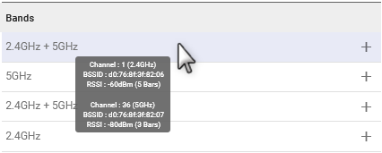
Tip: Hover the pointer on an SSID to view the channel, BSSID and RSSI for each band.
To use a scanned SSID:
- In the SCANNED SSIDS table, click SELECT to add the desired SSID to the SELECTED SSIDS table. You must then fully enable the new SSID by adding the SSID’s security passphrase.
- In the SELECTED SSIDS table, click edit
 for the desired Client SSID.
 - In the Edit SSID screen, add the security passphrase and assign a priority (optional).
- Click UPDATE.
 for the desired Client SSID.
After you configure the SSID with a passphrase, the Wi-Fi Client interface starts using it (if another SSID with a higher priority is not configured).

To create an SSID manually:
- Under the SELECTED SSIDS table, click CREATE SSID.
- In the Create SSID screen, enter the SSID name.
- Select the SECURITY MODE — Depending on the mode selected, specific security credential types are required:
- OPEN — No security. (This mode is NOT recommended.)
- WPA — Requires only a SECURITY PASSPHRASE (This mode is NOT recommended.)
- WPA2 — Requires a SECURITY PASSPHRASE, plus 802.11w options.
- WPA2/WPA3 Transition Mode — Requires a SECURITY PASSPHRASE, plus 802.11w options.
- WPA3 — Requires only a SECURITY PASSPHRASE.
- WPA2-Enterprise — Requires RADIUS Authentication & Acceptance server details.
- For all security modes except OPEN and WPA2-Enterprise, enter a SECURITY PASSPHRASE of at least 8 characters.
- For WPA2-Enterprise security mode only:
- Select the EAP METHOD to use. Options are:
- PEAP — when selected, requires the following:
- USER PASSWORD
- A ROOT CERTIFICATE. Optional. If required by RADIUS server, then select a certificate from the list, or select CREATE and enter the following:
SETTING DESCRIPTION TYPE Root Certificate NAME Required name identifying the certificate ROOT CERTIFICATE Click to upload the root certificate file
- TLS — when selected, requires the following:
- A USER CERTIFICATE WITH A ROOT CERTIFICATE. Select a certificate from the Uploaded certificates list or the Generated certificates list. If the certificate is not present, click CREATE and enter the following:
SETTING DESCRIPTION TYPE Certificate NAME Required name identifying the certificate PRIVATE KEY Click to upload the private key ROOT CERTIFICATE Click to upload the root certificate file
- For Generated certificates, clicking CREATE will open the Create Certificate Signing Request screen, where you can enter a certificate signing request to be sent to your certificate management system. See Managing Security Certificates for more information.
- A USER CERTIFICATE WITH A ROOT CERTIFICATE. Select a certificate from the Uploaded certificates list or the Generated certificates list. If the certificate is not present, click CREATE and enter the following:
- Certificates can also be created by going to System > Security > Certificates. See Managing Security Certificates for more information.
- As a client, it is the router's remote access point that passes the authentication to the RADIUS server.
Note:

- Optionally select the 802.11w. The 802.11w standard uses Security Association Query Requests to ensure that clients are legitimate. Options are:
- Disabled: not available as an option when WPA2/WPA3 Transition Mode is selected
- Optional (default): 802.11w will be used when connecting to access points that support it.
- Required: forces 802.11w operation; the router will not connect to access points unless they have 802.11w enabled.
- Enter the PRIORITY. Priority of networks ordered from 1 (high priority) to 65535 (low priority).
- Enter the RSSI THRESHOLD. Connects only if RSSI is above the specified threshold.
- For WPA2-Enterprise security mode only, enter the IDENTITY. The IDENTITY or username as defined on the RADIUS server
- Select CREATE.
When making a template to include the selected Client SSID with the enterprise certificates, the certificates will automatically be included in the template except for the private key. If the private key needs to be in the template, than like a password, it will need to be provided while in template creation mode.
Additional Client mode configuration
You can complete the Client mode configuration in the WI-FI INTERFACES table.

To configure an interface as a Client, click
at the end of the row of a Client interface.
The Edit Wi-Fi Interface menu appears — configure the fields in any order.
ENABLE the interface, and leave the MODE as Client.
Set the SSID SELECTION switch:
When you have multiple SSIDs configured, Sierra Wireless recommends leaving SSID SELECTION at the default Auto (Highest Priority) setting. The router will automatically search and connect to an SSID depending on priority. If priorities are identical, the router will use the closest SSID with the fastest estimated link speed. To configure the Wi-Fi client to use only a single, specific SSID, set SSID Selection to “Manual” and then choose the CONFIGURED SSID you wish to connect to.
- Enter the SCAN INTERVAL, which sets how often the router scans for SSIDs when disconnected.
- Set the BACKGROUND SCAN switch, which enables or disables the router scanning and connecting to higher priority SSIDs while already connected.
- Enter the BACKGROUND SCAN INTERVAL, which sets how often the router scans for other SSIDs when connected.

Monitoring Client Mode Operation
On Status/Monitoring > Dashboard, the WAN dashboard shows you the Wi-Fi WAN interfaces. A grey Wi-Fi icon (![]() ) indicates a disconnected interface. A blue Wi-Fi icon (
) indicates a disconnected interface. A blue Wi-Fi icon (![]() ) indicates a connected interface.
) indicates a connected interface.
Tip: Click a Wi-Fi icon to go to the WI-FI INTERFACES configuration table and review your configuration.

Additionally, you can go to Status/Monitoring > System > Wi-Fi to view detailed Wi-Fi Client status, including bitrate and the active channel.
