Connecting HL module-based Arduino application to AirVantage
 Searching...
Objective
This tutorial describes how to create communication between AirVantage and Arduino-based system equiped with an AirPrime HL wireless module. The following use cases are covered:
- Sending custom data such as sensor values or application data from Arduino to AirVantage
- Sending commands or configuration from AirVantage to Arduino
To implement this solution, MQTT protocol will be used.
Let’s develop a simple Alarm system to better showcase the solution in 4 main steps:
- Setup Arduino Hardware
- Setup Arduino Software Development Environment
- Define Arduino-AirVantage Interface
- Develop a simple Alarm system
Prerequisite
Important Note: The current HL Shield is no longer available for sale. This tutorial is still available as it illustrates how to use an HL with AT commands to send MQTT messages.
- HL Shield + Antenna + Power adaptor + USB cable MiniB-A
- AirPrime HL series Module
- SIM card with data call plan
- Arduino Mega2560 + USB cable type B-A
- USB Hub (3 ports or more) + TTL to Serial USB cable (E.g. TTL-232R)
- LED + PIR Motion detection sensor
- Female to female wiring cable
- Have an account on AirVantage server : eu.airvantage.net
Part references used in this tutorial
- AirPrime HL8548 module
- Arduino Mega 2560
- HL Shield: Please contact your local Sierra Wireless Technical representative
- Antenna
- Power adapter 12Vdc 1.5A
- USB Hub
- TTL to Serial USB cable
- USB-A to USB-B cable
- USB-A to MiniUSB cable
- Passive Infra-Red (PIR) motion sensor
- LED
- Wiring cables


Any issues ?
If you encounter any issue to set up your device, don’t hesitate to use the developer forum to benefit from the developer community experience.
Step 1: Hardware Setup
This step aims to setup the HL shield properly and stack it to Arduino Mega2560
Preparing the HL Shield
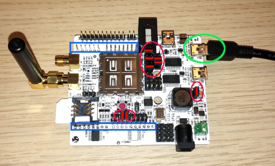
- Place the HL Module into the shield’s module socket. To ensure the correct orientation of the HL Module, use the dot mark, printed on the top right corner, as reference. It should be aligned with the dot mark visible within the shield socket. Then place the shielding cover on the module.
- Ensure that jumpers are correctly placed according to the photo (red marks in ellipses)
- Connect the antenna to the “2G/3G/4G RF MAIN” connector.
- Insert a SIM card into the “SIM1” slot, located in the bottom side of the Shield.
- Connect the “MAIN UART” USB port (green ellipse) to USB Hub which is connected to your PC/Mac
- If USB driver is missing, VCP driver can be downloaded here
Stacking HL Shield over Arduino
- Refer to the photo for stacking reference.
- Once stacked, Arduino’s I/O pins are exposed to the top of the HL Shield through staking headers, highlighted in blue rectangles of the previous photo.
- Note that there is no stacking header for pin #0 to #7, thus not accessible once stacked. Arduino’s RX and TX pins (0 and 1) are connected to module’s UART.
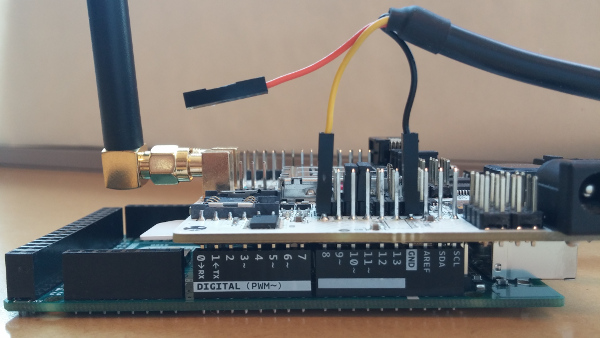
Connecting the Debug cable
- Connect the TTL to Serial Debug cable to Arduino’s pin #8 and GND as shown in the previous photo
- Pins #2 and #8 of Arduino will be configured programmatically as an serial port for debug output purpose
- Refer to the datasheet of your TTL cable, to perform the following connection:
- the TX wire cannot be connected to Arduino’s pin #2 (RX) as it is not accessible. Not an issue as Debug output does not make use of RX.
- the RX wire must be connected to Arduino’s pin #8 (TX)
- the Ground wire must be connected to Arduino’s GND pin
- Connect the TTL cable to USB Hub which is connected to your PC/Mac
- If USB driver is missing, VCP driver for FTDI-based TTL cables can be downloaded here
In Step 1, we’ve covered how to:
- Configure HL Shield and stack it over the Arduino Mega2560 board
- Connect HL Module’s UART to your host USB port
- Connect a debug cable (virtual serial port emulated on Arduino pin 2 & 8) to your host USB port
- Reference to USB driver has also been provided
Step 2: Software Installation
This step first introduce an overview of the embedded system to describe the various software components and their interactions with the development host (PC/Mac).
It will then guide you through the installation of the required software development environment and components
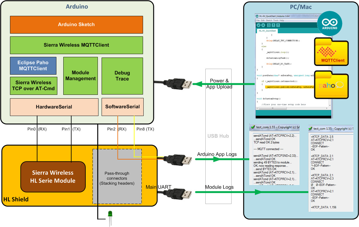
Embedded System Overview
- Arduino IDE will be used to develop then to upload the application to Arduino over the USB cable
- Sierra Wireless MQTT Client library (SWIR_MQTTClient) will be leveraged in order to easily establish communication between AirVantage and Arduino. This library provides 3 functionalities:
- Module management: setting SIM pin code, setting APN, making data call, etc…
- MQTT Client: managing MQTT session with AirVantage, sending/receiving MQTT packets over AT commands.
MQTT packets are generated and handled by Paho MQTTClient library which implements MQTT protocol. - Log output facility: SWI_TRACE macro enables the Arduino app to output debug traces to a virtual serial port. This latter function is emulated on Arduino pins 2 & 8 (by default) and trace logs are visible with a serial monitor application bound to the TTL to serial USB port.
- HL Shield wires Arduino’s default Serial port (pins 0 & 1) to HL module UART. Therefore, Arduino’s Serial object instance is used by SWIR_MQTTClient library to send AT commands to HL module, and shall not be used to output program trace log. For the latter purpose, use SWI_TRACE macro instead.
- HL module’s AT interface trace can be visualized with a serial monitor application bound to the HL Shield Main UART USB port.
Setup Embedded Software Development Components
- Download and install Arduino IDE.
- Launch Arduino IDE
- Import SWIR_MQTTClient library, V0.92
- Download the Arduino MQTTClient library for Sierra Wireless HL serie modules here
- In Arduino IDE, go to Sketch menu, select Include Library, then Add .ZIP Library…
- Select the SWIR_MQTTClient lib zip file as downloaded in the previous step (e.g. SWIR_MQTTClient V0.92.zip)
- Import Paho MQTTClient library
- Download the prebuilt Arduino port of Paho MQTTClient here
- In Arduino IDE, go to Sketch menu, select Include Library, then Add .ZIP Library…
- Select the Paho MQTTCleint zip file as downloaded in the previous step (e.g. arduino_1.0.0.zip)
Setup Debug output
- Unplug all USB plugs on the HUB Hub, while maintaining this latter plugged to your host computer. The intent here is to disconnect the host from all Arduino/HL Shield USB cables. All virtual COM ports are thus released on the host.
- Debug trace log for Arduino app
- Launch your favorite Serial monitor software or use the provided TestCom.exe
- Plug the TTL to Serial USB cable to the USB Hub, a virtual COM port shall be mounted accordingly
- Select this virtual COM port and choose 115200 baudrate to open this port in the Serial monitor application
- Output log for HL Module
- Launch a second instance of your favorite Serial monitor software or use the provided TestCom.exe
- Connect the HL Shield Main UART USB port to the USB Hub, a virtual COM port shall be mounted accordingly
- Select this virtual COM port and choose 115200 baudrate to open this port in the Serial monitor application
TestCom.exe tip: When plugging/unplugging a USB device, the associated virtual COM port is displayed in TestCom. Identifying the virtual COM to be openned is then made easy in the 2 above steps.
In Step 2, we’ve covered the following:
- Overview of the HL module-based Arduino system
- Installation of :
- Arduino IDE
- MQTTClient adapter Library for Sierra Wireless HL Serie Modules
- Paho MQTTClient Library
- Setup output tracing to view:
- Arduino application debug trace log
- HL Module’s AT interface trace log
Step 3: Arduino-AirVantage Interface
The Arduino-based embedded system has been properly setup in the previous steps. Before developping the Alarm System application on Arduino let’s:
- Define the interface between the Arduino and AirVantage: communication protocol, data flow and type.
- Check the MQTT connection between these 2 entities
Note that prior defining the client-server interface we’d need to define the Alarm System use case to figure out the necessary data flow and type.
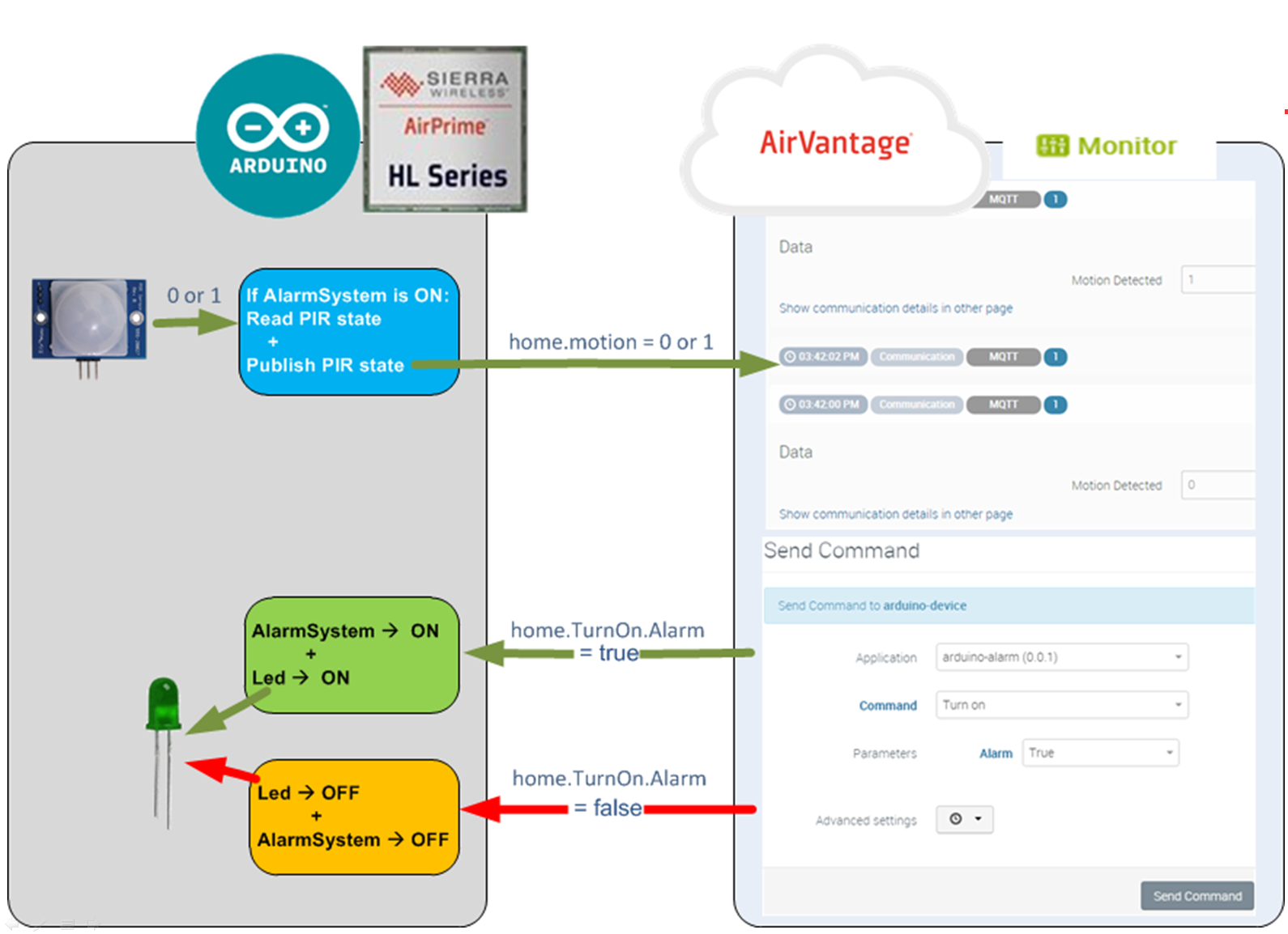
Alarm System Use Case
- On AirVantage portal, the user can turn ON or OFF the Arduino-based Alarm system
- If the Alarm is be turned ON, the Arduino shall arm the alarm and switch on the LED
- Then Arduino shall, on a regular basis, read motion event from PIR sensor, and publish it to AirVantage
- If the Alarm is to be turned OFF, the Arduino shall disarm the alarm system and switch off the LED
- Arduino shall not post any data to AirVantage
- The data flow and type are therefore defined as follow:
- TurnOn Action command from AirVantage to Device of type boolean. Value true for Turn ON, false for Turn OFF
- Motion event from Device to AirVantage of type integer. Value 1 for Motion detected, 0 for No Motion detected
Alarm System Application Model
- An embedded application on device-side (e.g. Arduino) is interfacing with a server-side application on AirVantage in order to exchange predefined data over a predefined communication protocol and authentication scheme:
- Server-side application is defined by an Application Model (a XML file)
- AirVantage uses this XML file to figure out how to deal with the device about Communication Protocol, Authentication and Data Exchange (e.g. variable, settings, commands)
Based on the use case as described in the previous section, the application model for our Alarm System is defined here:
- The communication protocol is MQTT, and the authentication is based on the device’s IMEI
<communication> <protocol comm-id="IMEI" type="MQTT" /> </communication>- The downstream TurnOn action command and the upstream motion event are defined in an asset labeled My Home, exchanged over MQTT protocol:
<data>
    <encoding type="MQTT">
        <asset default-label="My Home" id="home">
            <setting default-label="Motion Detected" path="motion" type="int"/>
            <command path="TurnOn" default-label="Turn on">
                <parameter id="Alarm" default-label="Alarm" type="boolean" />
            </command>
        </asset>
    </encoding>
</data>
The Application Model for our Alarm System is now defined. Let’s create it on AirVantage with the 2 following procedures:
Create Application Package
- Save the the Alarm Application Model to file with app file extension (e.g. appmodel.app)
- Zip the app file (e.g. appmodel.zip)
The filename of this zip file is only used for uploading process. AirVantage does not keep track of this zip filename. Only the XML content will be tracked by AirVantage.
- Log into AirVantage Web portal
- Go on Develop Activity > My Apps
- Click on the Release button


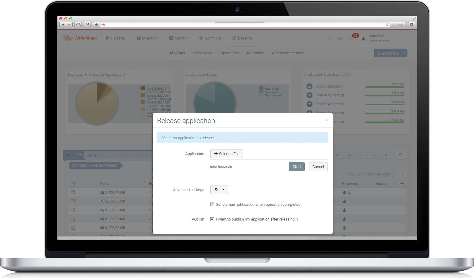
Release Application
- Select your zip file (e.g. appmodel.zip)
- Open Advanced settings and select I want to publish my application after releasing it
- Finally, click on Start
Making the First MQTT Connection
- Before developing the Alarm System application, let’s first try to make a MQTT connection between Arduino and AirVantage
- SWIR_MQTTClient Library provides a Quick Start sample Arduino sketch that is intended to be used as a starting point to easily build AirVantage-MQTT-ready application.
- This starting point Arduino application can publish data to and receive data from AirVantage… without typing a single line of code.
- In Arduino IDE, open the Quick Start sample sketch as follow: in File menu, go to Examples then SWIR_MQTTClient and select HL-AV_QuickStart
Adjust the SIM PIN code and APN for your SIM card, change the following definitions in the sketch if necessary:
#define APN                     "yourAPN"
#define APN_LOGIN               ""                          //your APN login
#define APN_PASSWORD            ""                          //your APN password
#define SIM_PIN_CODE            0                           //default is 0000, it's an integer!
Connect Arduino to USB Hub (to Host)
- In Arduino IDE, Tools menu, go to Board and select Arduino Mega or Mega2560
- In Tools menu, go to Port and select COMxx (Arduino Mega or Mega2560)
Make sure that the HL Shield is powered off (unplug power adapter)
Click the Upload icon on Arduino IDE, this will compile the sample sketch and upload the resulting binary to Arduino
Arduino sample app will automatically run upon sketch upload completion
Arduino app logs should be visible in the first serial monitor
Start the HL Module: power on the HL shield then press and hold the red button for 1 second
Arduino will attempt to establish MQTT session with AirVantage once data call is ready (module registered to network, CGREG = x,1 or x,5)
HL Module AT logs should be visible in the second serial monitor
Verifying MQTT Connection
The MQTT connection outcome (fail and success cases) are described hereafter.
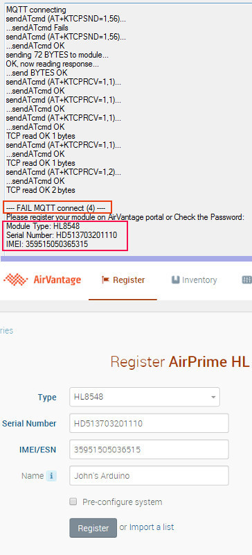
MQTT Connection Failed
- ”— Fail MQTT connect —” log (in serial monitor) indicates an unsuccessful MQTT connection, refer to top-right picture.
- This is the first connection, your HL Module has not been registered in AirVantage, let’s do the following:
- Log into AirVantage portal
- Release and Publish the Application Model as described in the previous sections Create Application Package and Release Application
- Register your system with below information, go to Register activity (refer to bottom-right picture)
- Select the Type of module (as displayed in the serial monitor)
- Copy the Serial Number displayed in serial monitor and pasted it into the Serial Number field
- Copy the IMEI 15-digits displayed in serial monitor and pasted it into the IMEI/ESN field
- Assign a Name
- Click on Register button
- Assign the Alarm Application Model to your device, go to Inventory activity then Systems
- Select your system, as registered in the above steps
- Click on the Edit icon

- In the Applications field, type in the name of the application (i.e. arduino-alarm) and select it
- Click on the Credentials icon

- Enter a password, it shall match the one in the sketch (#define MODULE_AV_PASSWORD), by default it is sierra
- Click on Save button
- From this point, the Arduino should be able to establish a MQTT session, continue the verification with the next sub-section MQTT Connected
- If you have already registered your HL Module on AirVantage portal, then make sure that:
- The Alarm Application Model with MQTT-binding has been created and assigned to your device, refer to case 2 above
- The password assigned in AirVantage to your System/AppModel is matching the one in the sketch (#define MODULE_AV_PASSWORD), it is sierra by default
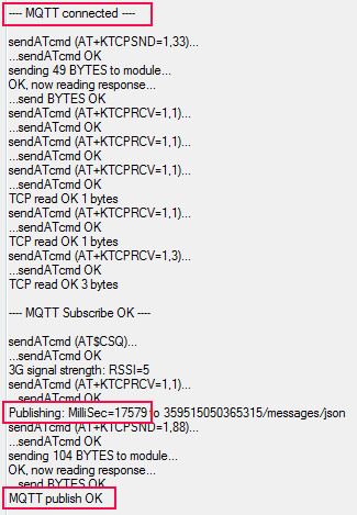
MQTT Connected
- Connected to AirVantage
- ”— MQTT connected —” log (in serial monitor) indicates a successful MQTT session
- ”— MQTT connected —” log (in serial monitor) indicates a successful MQTT session
- Sending data to AirVantage
- This sample application posts ellapsed milliseconds (since Arduino started) to AirVantage. The data key name is MilliSec
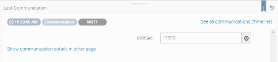
- To view the data being sent to AirVantage, log into AirVantage portal
- Go to your system monitor page (i.e. Monitor activity, go to Systems, then select Your System)
- Published data is visible in the Last Communication widget
- Receiving data from AirVantage
- This quick start sketch can also receive incoming data sent by AirVantage
- Log into AirVantage portal
- Go to your system monitor page (i.e. Monitor activity, go to Systems, then select Your System)
- Click on
 dropdown box then select Custom Command
 - In the Application field, select the alarm application (i.e. arduino-alarm)
- Choose a Command and define Parameters then click on Send Command
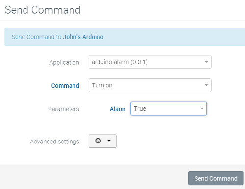
- This data should be received by the Arduino, it is displayed in the serial monitor
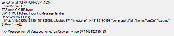
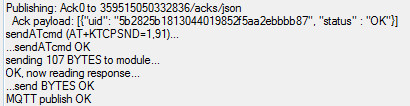
- Upon receiving command from AirVantage, the device should return an acknowlegment message back to AirVantage.
This ack message is automatically published (by the SWIR_MQTTClient library) to the /acks/json topic, as shown below


In Step 3, we’ve covered how to:
- Define the use case for the Alarm System which helps to figure out the data flow and type
- Create the Alarm Application Model that defines the interface between Arduino and AirVantage
- Make a first MQTT connection with AirVantage without coding
- Register device in AirVantage and then Assign Alarm Application Model to it
- Verify that Arduino can publish data to AirVantage
- Verify that Arduino can receive data from AirVantage
Step 4: Build an Alarm System
In this step, let’s modify the previous sample sketch to build a simple alarm system application. The use case of this Alarm application is described is the Step 3, section Alarm System Use Case.
Hardware Setup
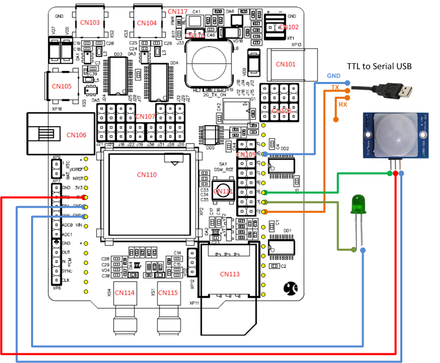
- Let’s wire the LED to Arduino’s digital pin #9 exposed to the top of the shield through stacking header, as shown in the picture
- The short leg pin of the LED shall be wired to the GND
- Wire the PIR’s Output to Arduino’s digital pin #10 exposed to the top of the shield through stacking header, as shown in the picture
- PIR’s GND and VCC pins shall wired to respectively Arduino’s GND and 5V pins
Application Development Guideline
- The QuickStart sketch, provided by the SWIR_MQTTClient library, should be used as a starting point to develop a new application.
It is structured as follow: - Configuration
- #define keyword is used to declare configurations which can adjusted by altering default values
- e.g. APN, SIM PIN code, Baudrate, MQTT quality of service level, delays, etc
- This is the right spot to declare additional data key names defined in your application model
- Global variables
- SWIR_MQTTClient object instance is needed as it is the interface with the Library
- A variable to keep track of the SIM status (ready or need SIM pin code)
- You may declare more variables to fulfill your needs
- QuickStart sketch provides a boilerplate code to facilitate the integration with AirVantage
- Check SIM pin, wait for readiness of data call, make MQTT connection, retry mechanism, perform regular task are handled in a proper sequence
- You can customize the application as follow:
- Add your one-time setup code in doCustomSetup() function, which is called by Arduino’s setup() function
- Add your code to be executed on a regular basis when MQTT session is established in doCustomLoopTask(), called by Arduino’s loop()
Usually, this is the placeholder to read sensor data and publish them to AirVantage - Add your code to execute incoming Commands from AirVantage in messageArrived() function
- Helper functions are provided for your convenience:
- PostData(keyName, value) to publish data (key/value) to AirVantage
- SWI_TRACE macro to print debug trace to serial monitor
Coding the Alarm System
Let’s code this application using the QuickStart sketch as a starting point, following the above guideline
Note the Alarm scenario specific code below can be be activated by enabling the flag ALARM_SCENARIO (#define ALARM_SCENARIO)In Arduino IDE, go to File menu then select Save As… to save the QuickStart sketch as a new sketch (e.g. AlarmApp)
Configuration:
- Add these new definitions for LED and PIR pins
#define ALARM_STATUS_LED_PIN 9 //the LED is wired to Arduino's digital pin #9 #define PIR_PIN 10 //the PIR is wired to Arduino's digital pin #10- Change data key name to match the ones defined in the Alarm Application Model (defined in Step 3)
- Data key names are prefixed with the asset id (i.e. home).
#define PUBLISH_DATA_NAME       "home.motion"
#define INCOMING_DATA_NAME      "home.TurnOn.Alarm"
Global variables:
- Declare this new global variable to track the Alarm status (on/off), default is off. Place this line before the setup() function.
int _isAlarmOn = 0;Configure the LED and PIR pins in the doCustomSetup() function
void doCustomSetup()
{
    pinMode(ALARM_STATUS_LED_PIN, OUTPUT);  //set LED pin as an OUTPUT
    pinMode(PIR_PIN, INPUT);                //set PIR pin as an INPUT
}
Publish the motion detection status to AirVantage in the doCustomLoopTask() function
void doCustomLoopTask()
{
    if (_isAlarmOn)
    {
        //At this point, the MQTT session has been established and the Alarm system has been armed
        if (digitalRead(PIR_PIN) == HIGH)
        {
            postData(PUBLISH_DATA_NAME, 1);     //Motion detected, let's post this event to AV
        }
        else
        {
            postData(PUBLISH_DATA_NAME, 0);     //No Motion detected, let's post this event to AV anyway
        }
    }
}
Handle AirVantage-originated Commands in the messageArrived() function
void messageArrived(const char* szKey, const char* szValue, const char* szTimestamp)
{
    SWIR_TRACE(F("\r\n>>> Message from AirVantage: %s = %s @ %s\r\n"), szKey, szValue, szTimestamp);
    //based on szKey and szValue let's turn on/off the alarm on/off LED
    String sKey = String(szKey);
    String sValue = String(szValue);
    if (sKey == INCOMING_DATA_NAME)
    {
        if (sValue == ON_VALUE)
        {
            digitalWrite(ALARM_STATUS_LED_PIN, HIGH);   //Switch ON LED
            _isAlarmOn = 1;                             //Arm the Alarm System
        }
        else
        {
            digitalWrite(ALARM_STATUS_LED_PIN, LOW);    //Switch OFF LED
            _isAlarmOn = 0;                             //Disarm the Alarm System


            postData(PUBLISH_DATA_NAME, 0);             //Publish message : "home.motion = 0", for consistency
        }


        return 0;                                       //to indicate that the command has been handled
    }


    return 1;                                           //to indicate unknown command,
                                                        //this information will be returned to AirVantage within the ACK message
}
Upload the Alarm sketch to Arduino
- Connect Arduino to USB Hub (to Host)
- In Arduino IDE, Tools menu, go to Board and select Arduino Mega or Mega2560
- In Tools menu, go to Port and select COMxx (Arduino Mega or Mega2560)
- Make sure that the HL Shield is powered off (unplug power adapter)
- Click the Upload icon on Arduino IDE, this will compile the sample sketch and upload the resulting binary to Arduino
- Arduino sample app will automatically run upon sketch upload completion
- Arduino app logs should be visible in the first serial monitor
- Start the HL Module: power on the HL shield then press and hold the red button for 1 second
- Arduino will attempt to establish MQTT session with AirVantage once data call is ready (module registered to network, CGREG = x,1 or x,5)
- HL Module AT logs should be visible in the second serial monitor
Testing the Alarm System
- Refer to Verifying MQTT Connection section in Step 3 to :
- Check the MQTT connection with AirVantage
- Remotely activate the Alarm system by sending Custom Command TurnOn.Alarm on AirVantage
- View motion detection events posted to AirVantage
In Step 4, we’ve covered :
- Arduino Hardware setup to fulfill the Alarm Use Case
- The guideline to easily develop an AirVantage-MQTT-ready application
- How to to develop the Alarm application using the QuickStart sketch as a starting point