Getting started with HL module on RaspberryPI
 Searching...
This tutorial describes how to create a communication with AirVantage Cloud from a RaspberryPI equiped with a HL wireless module. The following use cases are covered:
- Sending some custom data such as sensor value or application data from RaspberryPI to AirVantage Cloud
- Sending some commands or configuration from AirVantage Cloud to RaspberryPI
To implement this solution, MQTT protocol will be used
To achieve the above objective, following main steps are covered:
- How to setup your device: Hardware connection, AT command interface and IP connectivity
- How to register your device on AirVantage
- How to communicate with AirVantage using MQTT
Prerequisite
- Linkwave’s PiloT HL Shield for RaspberryPI + AirPrime HL module + Antenna
- RaspberryPI + SD Card with Raspian loaded + Power adaptor + keyboard + HDMI cable
- SIM card (Micro SIM format FF3) with data call plan
- Have an account on AirVantage server: eu.airvantage.net
Part references used in this tutorial


Any issues ?
If you encounter any issue to set up your device, don’t hesitate to use the developer forum to benefit from the developer community experience.
Step 1: Hardware setup
This step starts with interfacing the HL module with your Raspberry.
AT Command interface should then be in place to enable the host application to control the HL Module.
Finally, IP Connectivity is created using PPP dial-up to enable host applications to communicate with remote servers.
Connect Hardware
The HL Module should be in the PiloT’s module socket.
- Connect the antenna to the PiloT shield
- The SD card with Raspbian shall be inserted into the RaspberryPI
- Stack the PiloT Shield over the RaspberryPI
- Insert SIM card
- Select one of the following mean to access the Raspian console:
- Use USB Keyboard and HDMI cable for direct access to console
- Use Ethernet or WiFi for remote access to console with SSH
- Switch on the RaspberryPI

Interface with HL Module
The PiloT HL shield offers 2 hardware interfaces (USB or UART) for your RaspberryPI to control the HL module.
Select the hardware interface you’d like to use in this tutorial:
- The Raspberry PI serial port (UART) is /dev/ttyAMA0
- By default the Raspberry Pi’s serial port is configured to be used for console input/output. To be able to use the serial port to connect and talk to the HL module, the serial port console login needs to be disabled, as follow:
    Comment out the following line in /etc/inittab file:
    #T0:23:respawn:/sbin/getty -L ttyAMA0 115200 vt100
- After rebooting your RaspberryPI, AT commands can be issued over /dev/ttyAMAO
If you are using HL65xx module, module, GPIO6 and GPIO21 has to be configured as OUTPUT in order to enable Power supply and to turn on the module
- You can use different library/tool to setup these 2 GPIO, for instance: bw_rpi_tools or wiringPI .
Configure the following at every system reboot:
- Enable Power supply on the module : define GPIO6 as OUTPUT and set it to Logic 1 (HIGH)
- Turn On the module : define GPIO21 as OUTPUT, set it to Logic 1 (HIGH) for at least 2 seconds, then set it to Logic 0 (LOW)
Below is an example to turn on the HL65xx module using wiringPI library. Makefile and turnOnHL6.c
DEBUG   = -O3
CC      = gcc
INCLUDE = -I/usr/local/include
CFLAGS  = $(DEBUG) -c -Wall $(INCLUDE) -Winline -pipe
LDFLAGS = -L/usr/local/lib
LDLIBS  = -lwiringPi -lwiringPiDev -lpthread -lm
SOURCES = turnOnHL6.c
OBJECTS = $(SOURCES:.c=.o)
EXECUTABLE = turnOnHL6
all: $(SOURCES) $(EXECUTABLE)
$(EXECUTABLE): $(OBJECTS)
        $(CC) -o $@ $(OBJECTS) $(LDFLAGS) $(LDLIBS)
.c.o:
        $(CC) $(CFLAGS) $< -o $@
#include <stdio.h> #include <unistd.h> #include <wiringPi.h> #define GPIO_MODULE_ON 29 //this is BCM GPIO_21 #define GPIO_MODULE_POWER_ON 22 //this is BCM GPIO_06 int main() { //wiringPi lib setup wiringPiSetup(); //configure GPIO_21 & GPIO_06 as OUTPUT pinMode(GPIO_MODULE_ON, OUTPUT); pinMode(GPIO_MODULE_POWER_ON, OUTPUT); //set GPIO_21 and GPIO_06 to Logic 1 digitalWrite(GPIO_MODULE_POWER_ON, HIGH); digitalWrite(GPIO_MODULE_ON, HIGH); //wait for 5 seconds sleep(5); //set GPIO06 to Logic 0 digitalWrite(GPIO_MODULE_ON, LOW); return 0; }
USB Interface (Not Available with HL65xx Modules)
- Please note that USB interface is not available if HL65xx module is snapped in the PiloT shield
- Connect the PiloT shield’s micro USB port to RaspberryPI USB port, as shown in the picture
- Device ports ttyACM0 through ttyACM4 shall be available: /dev/ttyACM0 through /dev/ttyACM4
- AT commands can be issued over the following ports: ttyACM0, ttyACM3 and ttyACM4

Check AT-Command Interface
- Use a serial terminal (e.g. minicom) to make sure that the AT interface can be established. To install minicom proceed as follow (internet access required):
sudo apt-get install minicom
- Initialize the serial terminal to open the device port (e.g. /dev/ttyACM0 or /dev/ttyAMA0, depending of the hardware interface you’ve selected in the previous section) on which the HL module is attached to, for instance:
sudo minicom -D /dev/ttyAMA0
- The following AT commands shall be entered within minicom to perform some sanity checking:
- AT : expected response OK. If not, make sure the board is powered on (the VBAT led should be on) and check minicom baudrate setting (default HL baudrate should be 115200), using minicom -s
- AT+CPIN? : expected response READY
- if not, SIM PIN may be entered using the AT+CPIN command. e.g. AT+CPIN=“1234”
- AT+IPR? : the operating baudrate should be returned, please use this baudrate in the remaining tutorial
- AT+CREG? : to check the network registration status, expected response +CREG:x,1 (registered, home network) or +CREG:x,5 (roaming)
- AT+CGREG? : to check the GPRS registration status, expected response +CGREG:x,1 (registered, home network) or +CGREG:x,5 (roaming)
- AT+CSQ : returns “RSSI”,“BER”. RSSI indicates the signal strength in dBm, a value of 99 reflects no signal detected or not known
- Issue AT+CGSN command to retrieve module’s IMEI, please note the IMEI, it will be used in upcoming tutorial steps
- Issue AT+KGSN=3 command to retrieve module’s Serial Number, please note the S/N for future use
AT Commands Integration in the Device
In the above hands-on sections, we were able to manually send AT-Commands, using minicom. This sub-section aims to facilitate the AT-Command support within your device application.
Integration Helper
The aforementioned AT commands must be issued programmatically within your device application. And the response must be filtered and analyzed by the device application. For instance, the returned IMEI should be extracted from AT+CGSN response, IMEI is required to register the HL module on AirVantage platform. For your convenience, a sample AT command line tool can be adapted and integrated into your device application to rapidly gain AT-Command capabilities and to control the HL module. The provided sample AT command can also be used as is, as follow:
will return the filtered response which is the IMEI. Full response will be returned if no filter is specified. * ./hl-atcmd -d /dev/ttyAMA0 -b 115200 -f +KGSN: ‘AT+KGSN=“3”’
will return the filtered response which is the Serial Number. Full response will be returned if no filter is specified. * SIM PIN may be entered as follow: ./hl-atcmd -d /dev/ttyAMA0 -b 115200 ‘AT+CPIN=“1234”’ * Any AT-commands as documented in the AT-command specification can be executed using this command line (shell scriptable) * If the AT command is not responding, make sure that device port and the baudrate (AT+IPR?) are both correct.
In Step 1, we’ve covered how to:
- Connect HL Module to RaspberryPI
- Send AT Commands to HL Module
- Retrieve HL Modules’s IMEI & Serial Number using AT+CGSN & AT+KGSN=3 commands
Step 2: Setting up the connectivity
Setup PPP
PPP daemon (pppd) is available on Linux-based system. It can be installed on RaspberryPI as follow (internet access required):
PPP dial-up configuration is defined by a pppOptionFile, located in the /etc/ppp/peers directory. It is depending on a chatscript file (in /etc/chatscripts directory). The content of pppOptionFile is carrier specific and can be generated with pppconfig utility, refer to “man pppconfig” pages. Orange-France specific pppOptionFile and chatscript are provided here as example.sudo apt-get install ppp
Note that the device port and the baud rate are stated in the option file
Launch PPP
- Quit minicom before launching PPP
- Start PPP daemon by specifying the filename of the pppOptionFile (located in /etc/ppp/peers directory) as follow
sudo pppd call pppOptionFile &
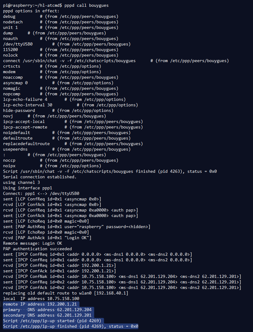
- The following statements in the log indicate a successful outcome of the PPP daemon:
- “local IP address…”, “remote IP address…”, “ip-up finished”
- PPP interface (e.g. ppp0) should be listed with associated IP address upon ifconfig commmand
- IP connectivity can be assessed with a ping command (e.g. ping www.google.com)
- When you will need to close the IP connectivity later, it is highly recommended not to stop the PPP daemon with CTRL-C. Proceed as following to properly terminate the PPP session:
- Issue ps -ef | grep pppd in the console
- Identify the pid associated to the running pppd process
- Issue sudo kill -s SIGHUP pid so the pppd will have the modem to hangup properly the data call.
In Step 2, we’ve covered how to:
- Use PPP dial-up to obtain IP Connectivity
Step 3: MQTT data exchange with AirVantage
MQTT is a lightweight publish/subscribe messaging protocol. A Device/Client application can publish a message to MQTT broker under a uniquely named topic. The server then instantly relays this message to other connected Device/Client applications having subscribed to the same named topic.
One-to-one and one-to-many IoT messaging approaches mechanism can thus come to life.
AirVantage server implements MQTT Broker functionalities. It has the ability to receive, to retain then to relay MQTT messages. AirVantage supports MQTT QoS Level 1 (messages delivered at least once with confirmation required).
This section starts with hands-on steps showing you how to publish messages to and receive data from AirVantage, using Mosquitto command line tools. Key integration aspects of MQTT client into your device application is then highlighted.
Any client implementing MQTT can be used to exchange data with AirVantage. In this tutorial, we will use Mosquitto , an open source solution implementing MQTT which can be installed on the host (e.g. run the following command for RaspberryPI or PC running Ubuntu) as follow (internet access required):
Publish MQTT Messages
MQTT messaging content exchanged between the Device and AirVantage Server is defined by Application Model and the payload should be JSON encoded:
- Each sample of a variable has a timestamp (elapsed ms since Jan-1970) and a value. It is possible to send a collection (or array) of sample at once.
- The variable is identified by it’s asset id and the path
- For instance, the following MQTT message to be published contains 2 samples of Temperature and Humidity variable as defined in Step 2-“Define Data Model”:
[ { "machine.temperature": [ {"timestamp": 1425937636000, "value":"21"}, {"timestamp": 1425939843000, "value":"20.9"} ] }, { "machine.humidity": [ {"timestamp": 1425937636000, "value":"37"}, {"timestamp": 1425939843000, "value":"38"} ] } ]- Below is another message example publishing temperature and humidity sample without specifying the timestamp. AirVantage will assign the current timestamp to samples.
{ {"machine.temperature" : "20.9"}, {"machine.humidity" : 38} }- Above message(s) shall be published to topic: “%SERIAL/messages/json”, where %SERIAL is the Serial Nuber of the module as retrieved in Step 1
Publish message to AirVantage, using Mosquitto command line:
- Save the above sample JSON message into a file (e.g. pub-msg.txt)
- Publish the file’s content to AirVantage, as follow
          *mosquitto_pub -h eu.airvantage.net -t %SERIAL/messages/json -f pub-msg.txt -u %SERIAL -P %password*<br>
            (where %SERIAL is the Serial Number of the module as retrieved in Step 1, %password is the password defined in Step 2)
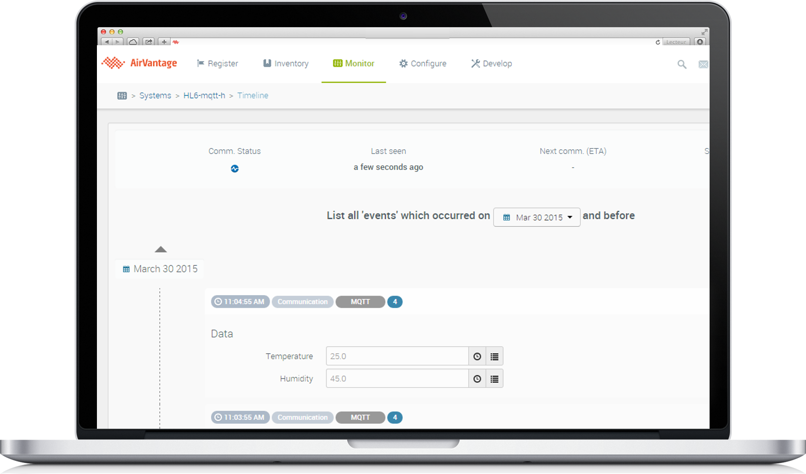
View Pusblished data on Web portal
Log into AirVantage Web portal
Go to Monitor > Systems
Search for your Systems/Device using filters (e.g. Label, Serial Number)
Click on your System/Device to view monitoring page
Scroll down to “Last Communication” panel to view data published by the Device
“Timeline” option can be used to view history events related to Device communication with AirVantage server
Subscribing to MQTT topic
In order to receive data from AirVantage, the device application must subscribe to the topic: “%SERIAL/tasks/json”.
Let’s do this using Mosquitto command line as follow:
    mosquitto_sub -h eu.airvantage.net -t %SERIAL/tasks/json -u %SERIAL -P %password
        (where %SERIAL is the SERIAL NUMBER of the module as retrieved in Step 1, %password is the password defined in your system)
Incoming data will be displayed as they arrive… now let’s send some data…
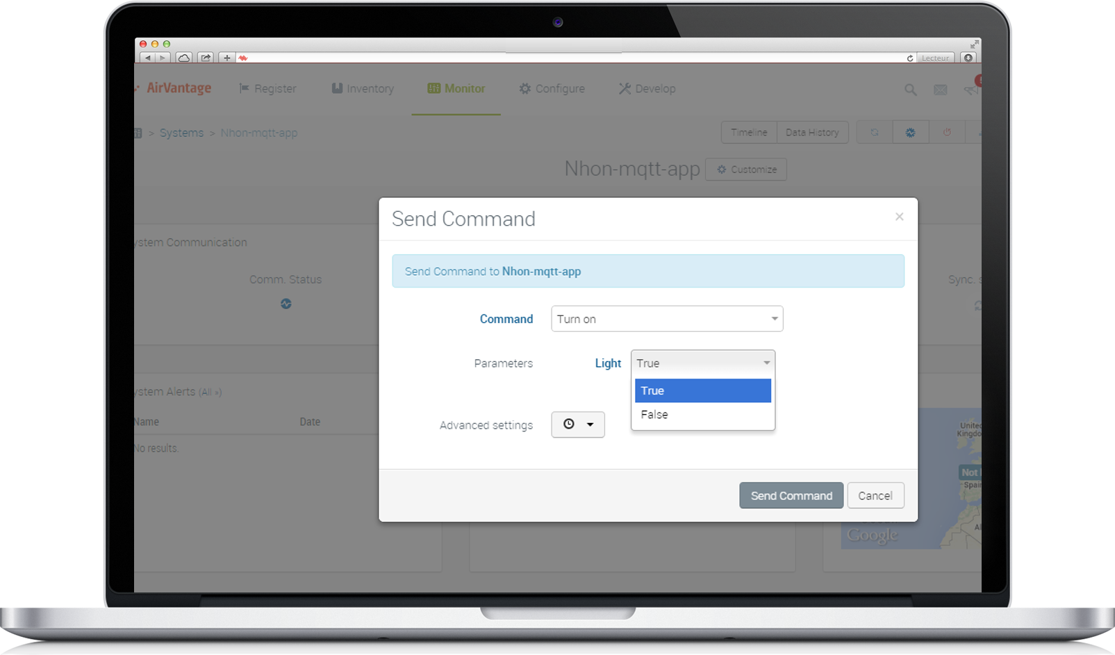
Sending MQTT data to Device from Web portal
- Go to Monitor > Systems
- Search for your Device using filters (e.g. Label, IMEI)
- Click on your Device to view monitoring page
- Click on the “More” button
 (located on top right), then select “Custom Command”
 - Base on the Greenhouse Application Model (excerpt below), the “Turn On” command can be sent to the Device from AirVantage Web portal:
<command path="TurnOn" default-label="Turn on">
<parameter id="Light" default-label="Light" type="boolean" />
- Select the action in the Command listbox and specify the corresponding parameters (e.g. Turn on Light)
- Click “Send Command” to fire the MQTT message to your Device
Receiving MQTT Messages
The incoming MQTT message should be displayed by the previous mosquitto_sub command as follow:
[{
  "uid":"9142df4c0b884683993521a3d5cf97f1",
  "timestamp":1426022121930,
  "command":{"id":"machine.TurnOn","params":{"Light":true}}
}]
This message is JSON encoded and must be decoded by the Device (handled by the callback function) as follow:
- uid is the unique id of this MQTT message. This uid must be used to acknowledge the command.
- timestamp is the jan-1970 elapsed timestamp of this message (in ms)
- command object is composed of :
- id: asset id (machine) and the command path (TurnOn)
- parameter id (Light) set to true
MQTT Client Integration in the Device
In the above hands-on steps, we were able to manually send messages to and receive data from AirVantage, using Mosquitto command line tools. This sub-section provides additional highlights on the integration of MQTT client into your device application. Addressing RaspberryPI’s GPIO is also briefly described.
MQTT Client Integration in the Device
The device application must implement MQTT Client functionalities in order to programmatically publish messages and to receive messages pertaining to subscribed topics. The specification can be found on http://mqtt.org .
There are various MQTT libraries available on the web that can be leveraged to easily gain MQTT support in the device application.
Most MQTT Client libraries expose 4 main functions: 1. Open Connection * The device application should call this function first with the following parameters: * AirVantage MQTT server URL and port number: (eu.airvantage.net:1883) * Device Serial Number (retrieved in step 1, “Send AT commands”), for authentication purposes * Password (as defined in AirVantage) 2. Message Publishing * The device application calls this function to publish the provided MQTT message (to be formatted as shown in step 3.2) to the specified Topic (URI style) * The publishing topic shall be “%SERIAL/messages/json”, where %SERIAL is the Serial Number of the module as retrieved in Step 1 3. Topic Subscription * The device app calls this function along with a Topic to subscribe to and a callback function to decode and parse the incoming MQTT message pertaining to the topic * The subscription topic shall be “%SERIAL/tasks/json”, where %SERIAL is the Serial Number of the module as retrieved in Step 1 4. Close Connection
Note that, in the previous hands-on section, the publishing command (mosquitto_pub) and subscription command (mosquitto_sub), are both encapsulated by Open connection and Close connection operations
Controlling RaspberryPI's GPIO
Controlling RaspberryPI’s GPIO
The wiringPI library can be easily integrated into the RaspberryPI in order to control GPIO. For instance, to turn on a LED wired to the GPIO-0 of the RaspberryPI when the device receives the above TurnOn Light command Below is the sample code:
#include <wiringPi.h>
...
wiringPiSetup();
pinMode(0, OUTPUT);
...
if (turnOnLight)
{
  digitalWrite(0, HIGH);
}
else
{
  digitalWrite(0, LOW);
}
Troubleshooting & Testing
Refer to this tutorial for further information on how to troubleshoot the connection and to interact with system/device
In Step 3, we’ve covered how to:
- MQTT Client integration into device and connection with AirVantage
- Formatting, encoding and Publishing MQTT message
- Viewing and collecting posted data on AirVantage
- Sending MQTT data to Device from AirVantage
- Subscribing, receiving, decoding incoming MQTT messages
- Sending command to RaspberryPI’s GPIO port
MQTT Sample Code
As described in the previous steps, enabling MQTT support in the device application requires the integration of MQTT protocol (may leveraging existing libraries). It also requires the implementation of JSON payload encoding/decoding and parsing/mapping of sensor/actuator/application data to the data model as defined in the application model.
Refer to sample applications below (C code) for integration reference.
Greenhouse
This sample (used in the above steps) publishes emulated Temperature and Humidity to AirVantage, and receives “TurnOn” command from AirVantage.
You may adapt this code to fit your needs.
MQTT Spooler
This application automatically converts CVS data to MQTT messages prior publishing to server. It also automatically converts incoming MQTT messages (pertaining to a subscribed Topic) to CSV data. This app could be reused as a quick integration option (no need to deal with MQTT code) with your existing sensor/actuator based application.