- Go to Networking > Firewall > Firewall Rules.
- Click CREATE FIREWALL RULE.
- The rule that you are creating will automatically be ENABLED. Click the switch to disable the rule if you are not ready to implement it right away.
- To turn on LOG ALERT, click the switch. When the rule is triggered by the firewall, a message will be stored in syslog.
- Set the RANK. The smaller the number, the higher the priority.
- Assign a NAME to describe the rule.
- Optionally identify the input traffic using SOURCE IP/NETWORK and/or INPUT ZONES/LAN SEGMENTS/INTERFACES and/or SOURCE PORTS.
- Optionally identify the output traffic using DESTINATION IP/NETWORK and/or DESTINATION ZONES/LAN SEGMENTS/INTERFACES and/or DESTINATION SERVICES.
If DESTINATION IP/NETWORK or DESTINATION ZONES/LAN SEGMENTS/INTERFACES is left blank, then it is considered router traffic. - Enter the ACTION to be taken. Options are DROP, REJECT, ALLOW.
Use DROP if the firewall rule is for traffic coming in from the internet. REJECT can be used for inside to outside traffic so that it returns a response to the local user. - Click CREATE to create the rule.
Configuring Firewall Rules
The Firewall configuration lets you establish rules that will allow you to monitor and control incoming and outgoing network traffic. The Firewall configuration is located at Networking > Firewall. Airlink OS uses a Zone-based firewall. For more information about Zones, see Configuring Zones.
By default, AirLink OS :
blocks all incoming unsolicited traffic packets
allows all LAN-to-LAN traffic
masquerades (Source Network Address Translation SNAT) on outbound traffic from the LAN interface
Specific firewall rules can be created to change this behavior.
 Initializing Table Of Contents...
Firewall Rules

The Firewall Rules table shows the user-defined rules.
| SETTING | DESCRIPTION |
|---|---|
| RULE STATUS | Number of rules that have been applied and how many are disabled. Any rules that are in the process of being implemented will not show in the RULE STATUS. |
| ALERT LOGGING | When enabled, any time a firewall rule is triggered, an alert will be logged in syslog. Default is Disabled. |
| LIMIT ALERTS PER MINUTE | Number of alerts per firewall rule that are logged in syslog. By default, alerts are limited to a maximum of 30 messages per minute. |
To configure a Firewall Rule

Firewall Status
The Firewall Status shows pre-defined system rules that have been created based on your configuration of the router. From the table you can enable or disable system rules. You can also turn on logging if you so desire
It is not possible to modify any system rule configuration settings directly.

There are two rules available to disable the system firewall rule for Masquerade (NAT) - one for IPv4 and another for IPv6. Both will need to be disabled if you wish to globally turn off masquerade.
If disabling masquerade is only needed on a per WAN basis, this can be done in Networking > General > WAN.
Configuring Firewall Port Forwarding Rules
To configure the Port Forwarding, see Configuring Port Forwarding.
Configuring DMZ Host
To configure the DMZ Host, see Configuring DMZ Host.
Configuring Reverse Path Forwarding
Reverse Path Forwarding (RPF) is used by firewalls to prevent IP address spoofing. Reverse Path Forwarding works by checking the source IP address of incoming packets against the routing table of the firewall. If the packet arrived on an interface that is not the best return path to reach the source IP address according to the routing table, the packet is dropped. This helps to ensure that the packet is legitimate and has not been spoofed.

To configure a Reverse Path Forwarding Rule
Go to Networking > Firewall > Reverse Path Forwarding.
Click CREATE REVERSE PATH FORWARDING
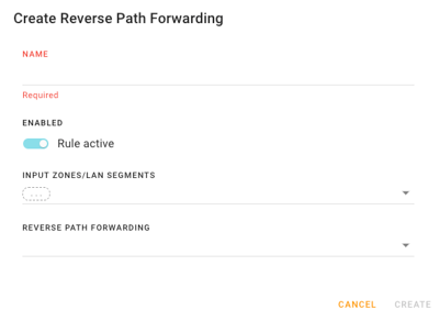
Enter a NAME.
To disable the rule, click the switch. The rule is active by default.
Under INPUT ZONES/LAN SEGMENTS, select an Input Zone and/or LAN segment and/or Interface. More than one can be selected.
Under REVERSE PATH FORWARDING, select an Input Zone and/or LAN segment and/or Interface. More than one can be selected.
Click CREATE to create the rule.
