Configuring VPN
The router can act as a Virtual Private Network (VPN) device, providing enterprise VPN access to any device connected to the router even when a device has no VPN client capability on its own. The router supports up to five simultaneous IPsec VPN tunnels. The IPsec implementation is fully IKEv1 and IKEv2 compliant, and supports MOBIKE when operating over IKEv2. The AirLink OS VPN implementation also provides the option to configure IPsec tunnels to FIPS (Federal Information Processing Standards) mode. You can configure VPN tunnels for LAN-terminated or Host-terminated applications.

 Initializing Table Of Contents...
Client Mode and Server Mode Compared
You can configure the XR Series router as a VPN client or VPN server. The table below outlines how the router operates in each mode.
| SERVER MODE | CLIENT MODE | |
|---|---|---|
| Overall relationship | Master – sets all details for connection, for all clients. AirLink XR Series routers running AirLink OS can support multiple clients connected simultaneously and are limited only by the throughput requirements of those clients. | Slave – must match the defined details for a single connection as defined on the target server |
| Tunnel specifications | Server defines/sets the configuration: authentication mechanism and details, network details | Client must match a configuration set on the server to which it is connecting |
| Network communication | Server defines what “enterprise” or central network(s) are available to remote clients, and what the expected remote network connection will look like (LAN or Host termination) | Client provides the remote network segment in LAN termination and may provide the individual host address for Host termination if the server does not have the ability to assign one |
| Routing | Server advertises routing information to the central network to access remote clients | Client provides routing for remote clients to access the central network |
| Connection details | Accepts or rejects tunnel connection requests | Requests a tunnel connection |
IPsec Tunnel Configuration Settings
These are the settings you will find in the Basic Configuration Steps described below. For Host-terminated applications, you must configure the virtual IP settings that control how the router acquires a virtual IP address (either automatically from the VPN server, or manually).
| SETTING | DESCRIPTION | DEFAULT SETTING | RANGE |
|---|---|---|---|
| NAME | Descriptive name for the tunnel | n/a | n/a |
| MODE |
Sets Client or Server mode for VPN operation. In Server mode, the router is configured to accept incoming tunnel requests and contains all details for all possible incoming connections. In Client mode, the router must match a unique configuration contained on the server to which it is connecting. |
Client | Client, Server |
| LAN/HOST MODE |
Select where the VPN tunnel terminates.
|
LAN | LAN, HOST |
| USE DEFAULT VIRTUAL IP POOL(S) | Appears when the tunnel is being configured for Server/HOST mode. | Enabled | Enabled, Disabled |
| VIRTUAL IP ADDRESS POOL(S) |
Appears when the tunnel is being configured for Server/HOST mode. In Server/HOST mode, the router allocates virtual IPv4 IP addresses from this pool. Note: Ensure that the Virtual IP address pool is uniquely routable in the network topology. The IP address range cannot be part of the network on the remote (Client) end. |
10.0.3.0/24 | IPv4 IP address |
| VIRTUAL IP ADDRESS POOL(S) |
Appears when the tunnel is being configured for Server/HOST mode. In Server/HOST mode, the router allocates virtual IPv6 IP addresses from this pool. Note: Ensure that the Virtual IP address pool is uniquely routable in the network topology. The IP address range cannot be part of the network on the remote (Client) end. |
2001:db8::3:0/24 | IPv6 IP address |
| CLIENT VIRTUAL IP TYPE |
Appears when the tunnel is being configured for Client/HOST mode. Selects how the virtual IP address is assigned. In most applications, Sierra Wireless recommends leaving this setting at Automatic, and the virtual IP address will come from the server’s configuration. If set to Static, the entered VIRTUAL IP ADDRESS (see below) will be used without requesting confirmation from the Server. |
Automatic | Automatic (requests a virtual IP address from the server), Static |
| VIRTUAL IP ADDRESS |
Appears when the tunnel is being configured for Client/HOST mode. When CLIENT VIRTUAL IP TYPE is Static, this is a required field. Only one address of an IP family is allowed. When CLIENT VIRTUAL IP TYPE is Automatic, any IP addresses entered here are requested from the server. The server may not return the same virtual IP addresses. Note: Static virtual IP addresses are ignored by Sierra Wireless ACM. The ACM assigns a virtual IP address from the subnet configured in the ACM. |
n/a | n/a |
| RANK |
When multiple IPsec tunnels are configured and the CONNECTION METHOD is set to Prioritized, the RANK determines the tunnel’s failover priority (1 being the highest rank; 100 the lowest). The highest-ranking established tunnel (as determined by the VPN Link Monitor) will be the active IPsec tunnel. An active IPsec tunnel will fail over to a lower-ranking tunnel if the active tunnel fails. You can also set the RANK in the TUNNELS table when the CONNECTION METHOD is set to Prioritized. |
1 | 1–100 |
| IKE VERSION | Sets the Internet Key Exchange (IKE) mode. The default setting of IKEv2 is required for FIPS mode and MOBIKE. You may need to select IKEv1 when the router is in Client mode and a third-party VPN appliance is not compatible with IKEv2. | IKEv2 | IKEv2, IKEv1 |
| MULTIPLE SA’s FOR IKEV2 | Enables compatibility with Cisco VPNs when multiple remote subnets are used in a single child SA. If you define multiple remote subnets under REMOTE SUBNETS, enable this setting to create a separate child SA for each remote subnet. | Disabled | Disabled, Enabled |
| MOBIKE |
In IKEv2 mode, enabling MOBIKE allows a VPN tunnel to stay connected, even if the WAN interface used by the tunnel changes. For example, the tunnel stays connected if the WAN interface changes from Ethernet to cellular. Note:
|
Enabled | Enabled, Disabled |
| AUTHENTICATION TYPE | Sets the authentication type/method | Certificate | Certificate, PSK |
| CERTIFICATES |
When AUTHENTICATION TYPE is Certificate, lets you add or create/upload PEM certificates for authentication. 
|
n/a | n/a |
| PSK |
When AUTHENTICATION TYPE is PSK, lets you set the pre-shared key for authentication.
|
n/a | n/a |
| PEERS | Required to identify the peer side of a VPN connection. This is the primary peer (see SECONDARY PEER FOR FAILOVER below) and can be an IP address or an FQDN. | n/a | IPv4, IPv6 |
| LOCAL SUBNETS | Enter the local address or subnet in CIDR notation; for example, 192.168.13.0/24 | n/a | n/a |
| REMOTE SUBNETS |
The IP address or subnet (in CIDR notation) of the device(s) connected to the remote VPN server. These addresses/subnets will be accessible from any hosts connected locally to the router. To configure a full tunnel, enter 0.0.0.0/0. To configure a split tunnel, enter the individual remote subnets. Note: Not available when configuring the tunnel for Server/HOST mode. |
n/a | n/a |
| EXEMPT SUBNETS |
List of Remote Addresses or subnets to be exempted. Traffic passing through the router to the IP addresses (or Fully Qualified Domain Names (FQDNs)) in this list is sent directly to the Internet, not through the IPsec VPN tunnel. Entering EXEMPT SUBNETS is useful in full tunnel Configurations (0.0.0.0/0 or ::/0), when you need to redirect certain subnets outside of the IPsec tunnel. |
n/a | n/a |
| LOCAL AUTHENTICATION ID | You can enter the Local Authentication ID as a text string to identify the router as a VPN client. The Local Authentication ID must also be configured on the remote VPN server (the Sierra Wireless ACM, for example). Alternatively, you can leave the Local Authentication ID blank to use the default WAN IP address. The default WAN IP address would also need to be configured on the remote server/ACM. | n/a | n/a |
| REMOTE AUTHENTICATION ID | The Remote Authentication ID configures how the router recognizes incoming traffic. This setting must match the server side. | n/a | n/a |
| WAN INTERFACES |
Select the WAN interfaces to use for this tunnel, in order of priority (first to last/left to right). The order specifies the sequence of failover if the highest-priority WAN interface loses connection. You can select default to have the tunnel use the default WAN zone. In that case, the default WAN priority of Ethernet, Wi-Fi and Cellular applies. The Multi-WAN policies Default IPv4 Traffic or Default IPv6 Traffic specify which outgoing WAN interface to use. Please note that even when default is not selected, the tunnel will use the default WAN interface if no other configured WAN interface is available. If you select a custom list of WAN interfaces, then the Multi-WAN Policy for the tunnel in IPsec Policies for Client Tunnels will be created and used. See Multi-WAN Policies below. |
List of enabled WAN Interfaces (varies by router model). | |
| START | Enable the IPsec tunnel and connect to the configured peer. Takes effect after you click CREATE. | Disabled | Disabled, Enabled |
| DEAD PEER DETECTION (DPD) |
Dead Peer Detection (DPD) verifies the status of the active connection, and can be configured to take action if the primary/active VPN tunnel goes down. Possible actions when DPD detects a failed connection are:
For more information, see VPN Failover. |
Restart | Restart, None, Failover |
| SECONDARY PEER FOR FAILOVER |
When DEAD PEER DETECTION is set to Failover, enter the secondary peer that will take over from the primary peer. This can be an IP address or an FQDN. 
|
n/a | n/a |
| DPD INTERVAL (SECONDS) | Sets the DPD interval (in seconds). If there has been no traffic during this interval, after five retries (each with an interval of 30 seconds by default) the router takes the DPD action configured above. | 30 | 30–3600 |
| IKE REKEY TIME (SECONDS) | Sets how long the VPN tunnel is active, in seconds | 7200 | 60–32000000 |
| IKE ENCRYPTION | Sets the type and length of encryption key used to encrypt/decrypt IKE packets. IKE Encryption is the first stage of encryption. More bits in the encryption key increases the security of the traffic, but this also increases the processing load and reduces the number of simultaneous clients the router can support. | aes256 |
|
| IKE INTEGRITY | Sets the type and length of digest used for authentication. | sha256 | sha256, sha384, sha512 |
| IKE DIFFIE-HELLMAN GROUPS |
Use this field to select the DH (Diffie-Hellman) group pre-shared key length used for authentication. The DH group number determines the length of the key used in the key exchange process. Longer keys are more secure, but take longer to compute. Also note that both peers in the VPN exchange must use the same DH group. |
dh16 (modp4096) |
|
| PERFECT FORWARD SECURITY (PFS) | PFS adds additional security because each session uses a unique temporary public/private key pair to generate the shared secret. One key cannot be derived from another. This ensures previous and subsequent encryption keys are secure, even if one key is compromised. | Enabled | Enabled, Disabled |
| ESP REKEY TIME (SECONDS) | Sets how long the VPN tunnel is active, in seconds | 7200 | 60–32000000 |
| ESP ENCRYPTION | Sets the type and length of encryption key used to encrypt/decrypt ESP (Encapsulating Security Payload) packets. ESP Encryption is the second stage of encryption. More bits in the encryption key increases the security of the traffic, but this also increases the processing load and reduces the number of simultaneous clients the router can support. | aes256 |
|
| ESP INTEGRITY | Sets the type and length of digest used for authentication | sha256 |
|
| ESP DIFFIE-HELLMAN GROUPS | Use this field to select the DH (Diffie-Hellman) group key length used for authentication. The DH group number determines the length of the key used in the key exchange process. Longer keys are more secure, but take longer to compute. Also note that both peers in the VPN exchange must use the same DH group. | dh16 (modp4096) |
|
| VPN LINK MONITORS |
Select one or more configured VPN LINK MONITOR(S) for the tunnel to use. The Link Monitor will restart the VPN tunnel if there is a ping failure. When you have multiple Link Monitors selected, the first Link Monitor that detects a connection failure will trigger a tunnel restart. See Configuring VPN Link Monitors for more information. 
|
n/a | n/a |
Basic Configuration Steps
To begin configuring a VPN tunnel:
Go to Networking > VPN > IPsec Tunnels.
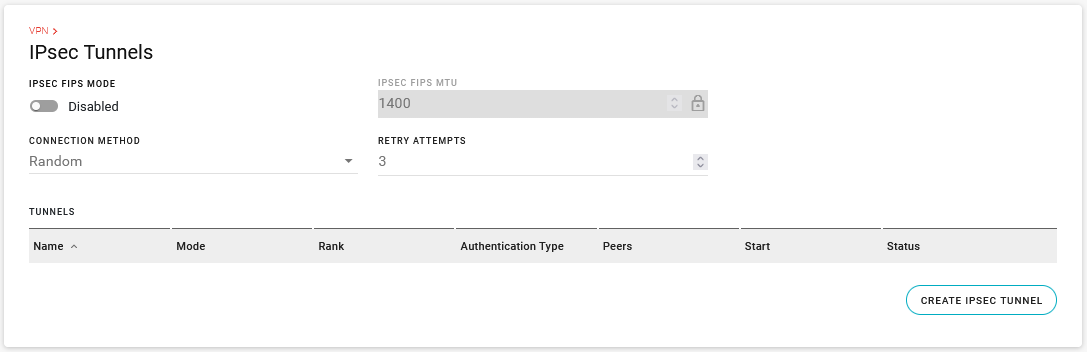
Enable IPSEC FIPS MODE, if required. When enabled, a FIPS-approved cryptographic module is used for IPsec data protection, and only FIPS-approved cryptographic algorithms are allowed for tunnel configurations. Note: FIPS is only supported for IKEv2 tunnels.
Select IPSEC FIPS MTU if IPSEC FIPS MODE is enabled (default is 1400; range is 100–1500). This sets the maximum transmission unit size for IPsec packets before encryption.
Select the CONNECTION METHOD if you plan to configure multiple IPsec tunnels in Client mode. The CONNECTION METHOD gives you options for IPsec tunnel failover. The options are:
- All: All tunnels attempt to connect simultaneously.
- Random: AirLink OS establishes the connection by selecting a random tunnel from the list of configured tunnels. If a tunnel goes down, as determined by the VPN Link Monitor, AirLink OS randomly selects another tunnel from the list of configured tunnels.
- Prioritized: AirLink OS establishes the connection by selecting the highest ranking tunnel in the list of configured tunnels. If a tunnel goes down, as determined by the VPN Link Monitor, AirLink OS selects the next highest-ranking tunnel. Ensure that each tunnel has a unique rank in the list. You can set a tunnel’s rank when you configure the IPsec Tunnel, or in the TUNNELS table when the CONNECTION METHOD is set to Prioritized.
If the CONNECTION METHOD is Random or Prioritized, select the number of RETRY ATTEMPTS (default is 3; range is 0–10). This sets how many consecutive times an IPsec tunnel tries to connect before the next tunnel is used. Setting RETRY ATTEMPTS to 0 switches to the next tunnel immediately after first connection failure. The interval between retry attempts is set by a default backoff timer. This timer increases after each failed retry attempt from 10 seconds to a maximum of 600 seconds.
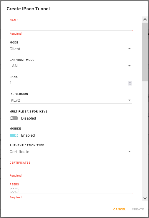
Click CREATE IPSEC TUNNEL.
Configure the router’s VPN mode and type of IPsec tunnel for your desired application. The following options are available:
- Client mode, LAN-to-LAN tunnel
- Client mode, HOST-to-LAN tunnel
- Server mode, LAN-to-LAN tunnel
- Server mode, HOST-to-LAN tunnel
Click CREATE.


Configuring a LAN-to-LAN tunnel in Client mode
The settings in the procedure below are described in the IPsec Configuration Settings table above.
To configure a LAN-to-LAN tunnel in Client mode:
- Enter a tunnel NAME.
- Set the router’s VPN MODE to Client.
- Set the LAN/HOST MODE to LAN.
- If you plan to use multiple IPsec tunnels in Client mode, set the RANK for failover priority.
- Select the IKE VERSION. When IKE VERSION is set to IKEv2, you can enable or disable:
- MULTIPLE SA’S FOR IKEV2
- MOBIKE
- Select the AUTHENTICATION TYPE.
- After selecting Certificates, you must select any existing PEM Certificates on the router, or upload the certificate components to the router.
- After selecting PSK, you must enter a text string for the pre-shared key.
- Enter the PEERS as one or more IPv4 or IPv6 IP addresses.
- Enter LOCAL SUBNETS, REMOTE SUBNETS and any EXEMPT SUBNETS.
- Enter LOCAL AUTHENTICATION ID and REMOTE AUTHENTICATION ID to match the credentials for your VPN server.
- Select the WAN INTERFACES for VPN traffic to and from the router, in order of priority.
- Select whether to START the tunnel when you finish configuration and click CREATE.
- Configure DEAD PEER DETECTION, if desired (requires you to configure the SECONDARY PEER FOR FAILOVER).
- Configure IKE settings.
- Select whether to use PERFECT FORWARD SECURITY (PFS).
- If PFS is enabled, configure ESP settings.
- Select VPN LINK MONITORS.
- Click CREATE.

Configuring a HOST-to-LAN tunnel in Client mode
The settings in the procedure below are described in the IPsec Configuration Settings table above.
To configure a HOST-to-LAN tunnel in Client mode:
- Enter a tunnel NAME.
- Set the router’s VPN MODE to Client.
- Set the LAN/HOST MODE to HOST.
- If you plan to use multiple IPsec tunnels in Client mode, set the RANK for failover priority.
- Select the CLIENT VIRTUAL IP TYPE.
- Enter a VIRTUAL IP ADDRESS, if required by the CLIENT VIRTUAL IP TYPE.
- Select the IKE VERSION. When IKE VERSION is set to IKEv2, you can enable or disable:
- MULTIPLE SA’S FOR IKEV2
- MOBIKE
- Select the AUTHENTICATION TYPE.
- After selecting Certificates, you must select any existing PEM Certificates on the router, or upload the certificate components to the router.
- After selecting PSK, you must enter a text string for the pre-shared key.
- Enter the PEERS as one or more IPv4 or IPv6 IP addresses.
- Enter LOCAL SUBNETS, REMOTE SUBNETS and any EXEMPT SUBNETS.
- Enter LOCAL AUTHENTICATION ID and REMOTE AUTHENTICATION ID to match the credentials for your VPN server.
- Select the WAN INTERFACES for VPN traffic to and from the router, in order of priority.
- Select whether to START the tunnel when you finish configuration and click CREATE.
- Configure DEAD PEER DETECTION, if desired (requires you to configure the SECONDARY PEER FOR FAILOVER).
- Configure IKE settings.
- Select whether to use PERFECT FORWARD SECURITY (PFS).
- If PFS is enabled, configure ESP settings.
- Select VPN LINK MONITORS.
- Click CREATE.

Configuring a LAN-to-LAN tunnel in Server mode
The settings in the procedure below are described in the IPsec Configuration Settings table above.
To configure a LAN-to-LAN tunnel in Server mode:
- Enter a tunnel NAME.
- Set the router’s VPN MODE to Server.
- Set the LAN/HOST MODE to LAN.
- Select the IKE VERSION. When IKE VERSION is set to IKEv2, you can enable or disable:
- MULTIPLE SA’S FOR IKEV2
- MOBIKE
- Select the AUTHENTICATION TYPE.
- After selecting Certificates, you must select any existing PEM Certificates on the router, or upload the certificate components to the router.
- After selecting PSK, you must enter a text string for the pre-shared key.
- Enter the PEERS as one or more IPv4 or IPv6 IP addresses.
- Enter LOCAL SUBNETS, REMOTE SUBNETS and any EXEMPT SUBNETS.
- Enter LOCAL AUTHENTICATION ID and REMOTE AUTHENTICATION ID to match the credentials for your VPN server.
- Select the WAN INTERFACES for VPN traffic to and from the router, in order of priority.
- Select whether to START the tunnel when you finish configuration and click CREATE.
- Configure DEAD PEER DETECTION, if desired (requires you to configure the SECONDARY PEER FOR FAILOVER).
- Configure IKE settings.
- Select whether to use PERFECT FORWARD SECURITY (PFS).
- If PFS is enabled, configure ESP settings.
- Click CREATE.

Configuring a HOST-to-LAN tunnel in Server mode
The settings in the procedure below are described in the IPsec Configuration Settings table above.
To configure a HOST-to-LAN tunnel in Server mode:
- Enter a tunnel NAME.
- Set the router’s VPN MODE to Server.
- Set the LAN/HOST MODE to HOST.
- Enable or disable USE DEFAULT VIRTUAL IP POOL(S).
- Enter the VIRTUAL IP ADDRESS POOL(S) (IPv4 or IPv6), if you have disabled USE DEFAULT VIRTUAL IP POOL(S).
- Select the IKE VERSION. When IKE VERSION is set to IKEv2, you can enable or disable:
- MULTIPLE SA’S FOR IKEV2
- MOBIKE
- Select the AUTHENTICATION TYPE.
- After selecting Certificates, you must select any existing PEM Certificates on the router, or upload the certificate components to the router.
- After selecting PSK, you must enter a text string for the pre-shared key.
- Enter the PEERS as one or more IPv4 or IPv6 IP addresses.
- Enter LOCAL SUBNETS and any EXEMPT SUBNETS.
- Enter LOCAL AUTHENTICATION ID and REMOTE AUTHENTICATION ID to match the credentials for your VPN server.
- Select whether to START the tunnel when you finish configuration and click CREATE.
- Configure DEAD PEER DETECTION, if desired (requires you to configure the SECONDARY PEER FOR FAILOVER).
- Configure IKE settings.
- Select whether to use PERFECT FORWARD SECURITY (PFS).
- If PFS is enabled, configure ESP settings.
- Click CREATE.

Router Initiated Traffic
By default, router initiated traffic, such as communications to ALMS, is sent outside the VPN tunnel. In some cases, you may want to have all traffic including router traffic to go through the VPN tunnel. To accomplish this, you will need to create SNAT rules. Refer to Network Address Translation Rules for further information.
IPsec Status
Go to Status/Monitoring > Networking > IPsec Status to view IPsec tunnel status.
The IPSEC STATUS TABLE shows you the main status items. You can click  at the end of each row to view more information.
- Click the UPDATE INTERVAL field to change the UPDATE INTERVAL. Enter a new interval (the ranges is 30 to 86400 seconds) and then click TAB or ENTER.
- Click REFRESH to view the latest status without waiting for the UPDATE INTERVAL to elapse.

VPN Failover
AirLink OS has two VPN failover mechanisms that will help maintain your VPN connection.
VPN Link Monitors
VPN Link Monitors in combination with Connection Method can be used when you have multiple tunnels configured. The VPN Link Monitors use pings to verify the connection of the IPsec tunnel, and the Connection Method determines which alternate IPsec tunnel to use if the Link Monitors detect a connection failure.
Dead Peer Detection
Dead Peer Detection (DPD) monitors incoming traffic flow and selects a secondary peer or restarts the tunnel if no incoming traffic is detected for a configured interval. Dead Peer Detection can be slower to respond to connection issues than the VPN Link Monitor, but, unlike the Connection Method option, does not require that you configure multiple IPsec tunnels for failover.
To use DEAD PEER DETECTION (DPD) to help maintain your VPN connection, set DEAD PEER DETECTION (DPD) to Failover, and configure a secondary VPN peer. Dead Peer Detection (DPD) verifies the status of the active connection. For example, if the primary/active VPN goes down (that is, DPD detects that the end device is not responding), you can configure the VPN to automatically switch traffic to a backup VPN tunnel (the secondary peer).
By default, Dead Peer Detection begins 30 seconds after no incoming traffic is detected. After five retries at 30-second intervals (by default), traffic failure is confirmed. VPN traffic then “fails over” to the backup VPN tunnel.
The number of retries is not configurable, and the interval can be a minimum of 30 seconds.
After failover, the secondary peer becomes the primary. If the original primary peer comes back online, the VPN does not automatically switch back until another transmission failure is detected and failover happens again. Rebooting the router also restores the primary peer, if it is online.

Multi-WAN Policies
After you have created an IPsec VPN tunnel, you can add the tunnel to a Multi-WAN rule to help steer and optimize how the tunnel uses its assigned WAN interfaces.
Under Multi-WAN Policies, the IPSEC POLICIES FOR CLIENT TUNNELS table displays your configured VPN tunnels, with each tunnel’s configured WAN outputs, in priority, and the WAN interface that is currently active.

You can apply any Multi-WAN Rule (Roaming, Signal Strength, Wi-Fi SSID, or Speed) to a VPN tunnel to influence which WAN interface the VPN uses. For more information on Multi-WAN Policies, see Configuring Multi-WAN Policies.

Only IPsec VPN tunnels that have a custom ordering of WAN interfaces (configured in WAN INTERFACES as described in the IPsec Configuration Settings table) appear in the IPSEC POLICIES FOR CLIENT TUNNELS table.
IPsec VPN tunnels that use the default WAN zone do not appear in the IPSEC POLICIES FOR CLIENT TUNNELS table. Instead, they use the Default IPv4 Traffic or Default IPv6 Traffic System Policies, which by default use the default WAN zone.
You can view the default WAN zone interface priority under Networking > Zones Settings > SYSTEM ZONES.
If you want to modify the default WAN priority, click the WAN Output(s) field for the Default IPv4 Traffic or Default IPv6 Traffic Policies, and add interfaces to that policy. Alternatively, you can create a new Zone containing the interfaces in the priority you want. Click CREATE, and add interfaces or LAN segments in the desired order.
You can then add the modified Multi-WAN System policies to Multi-WAN rules to control how the IPsec VPN tunnels use their assigned WAN interfaces.