Using MQTT with an HL Shield and a ST Nucleo
 Searching...
This article explains how to send data to AirVantage for mbed devices using MQTT and an HL shield. It will focus on two boards: the ST Nucleo and the HL Shield. As the ST Nucleo board is a microcontrol without any IP stack, it requires to use the HL one. Consequently, all the interactions is done using AT commands. You can see more about this, in the Step 3 below.


Prerequisite
You must have:
- A basic knowledge of MQTT. See the other tutorials about MQTT for airvantage and specifically MQTT API.
- A basic knowledge of c.
- A basic knowledge on mbed development
- An Internet access with an HL6* or an HL8 shield
- A ST Nucleo L053R8 (the software has been specifically developed with this target. It may work with another ST Nucleo board with slight changes).
*) For HL6, the sample must be modified (function
MQTTClient::getIMEIin the fileMQTTClient.cpp) to get the IMEI. The commandAT+CGSNmust be used instead of the commandAT+KGSN=0.
Step 1: Setup Hardware
The ST Nucleo L053R8 has been used for the development. There are some particularities about this board.
ST Nucleo (L053R8)
By default, the RX, TX pins are on CN3 and not on CN9. It means that the pins layout is not fully Arduino compatible. You can’t plug the two boards directly. You need to connect them using wires.
Another way is to modify the Solder Bridge as described in the following document.

HL Shield
The HL shield must have their inputs/outputs powered by the ST Nucleo board. If not, the TX signal from the HL shield will not be read by the ST Nucleo board. For more information, you can check in the file Design of the DistriKit Board .

Connection
The 2 boards need to be connected. You must follow this wiring:
| ST Nucleo | HL Shield |
|---|---|
| TX (CN3) | RX (XP4) |
| RX (CN3) | TX (XP4) |
| IOREF (CN6) | IOREF (XP3) |
| GND (CN6) | GND (XP3) |
Step 2: Design your application
An application model aims to explain to AirVantage how to deal with the device about communication and authentication and managing the data: variable, settings or commands. If you don’t supply such information, the server will not understand and be able to use the raw data from your device.
This application is already deployed on AirVantage in the public repository under the name Distri Kit version 1.0.0. You can use this one or create a new application for your company using an other name.
Define your data
- First of all, to be able to send and receive data, you have to describe your data to AirVantage. Here is the description, you just need to change the type value with a unique identifier for your application and the name and revision with the appropriate values for your use case.
- You can modify the
<data>area. Once it matches your needs, save everything as model.app.
Don’t modify the asset id as it is used in the source code application or modify it accordingly.
<?xml version="1.0" encoding="ISO-8859-1"?>
<app:application
        xmlns:app="http://www.sierrawireless.com/airvantage/application/1.0"
        type="com.test.airvantage.app"
        name="AirVantage Greenhouse"
        revision="0.0.1">
  <capabilities>

    <communication>
      <protocol comm-id="IMEI" type="MQTT" />
    </communication>

    <data>
      <encoding type="MQTT">
        <asset default-label="Street Light" id="st">
          <variable default-label="Light Control" path="lightstatus" type="string"/>
          <variable default-label="Light Sensor" path="lightsensor" type="int"/>
          <variable default-label="Output Power" path="power" type="int"/>
          <variable default-label="Failure Detected" path="failuredetected" type="boolean"/>
          <command default-label="Manual OFF" id="modeoff">
          </command>
          <command default-label="Mode Auto" id="modeauto">
          </command>
          <command default-label="Manual ON" id="modeon">
          </command>
        </asset>
      </encoding>
    </data>
  </capabilities>
</app:application>
Create your application package
- Zip this file, mine is named model.app.zip
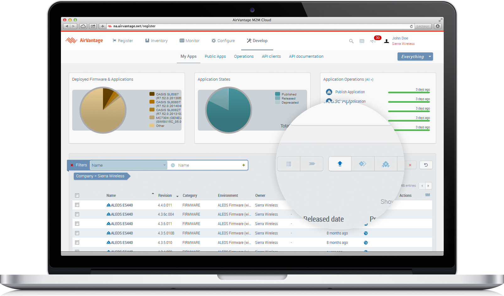
- Go on Develop Activity > My Apps
- Click on the Release button
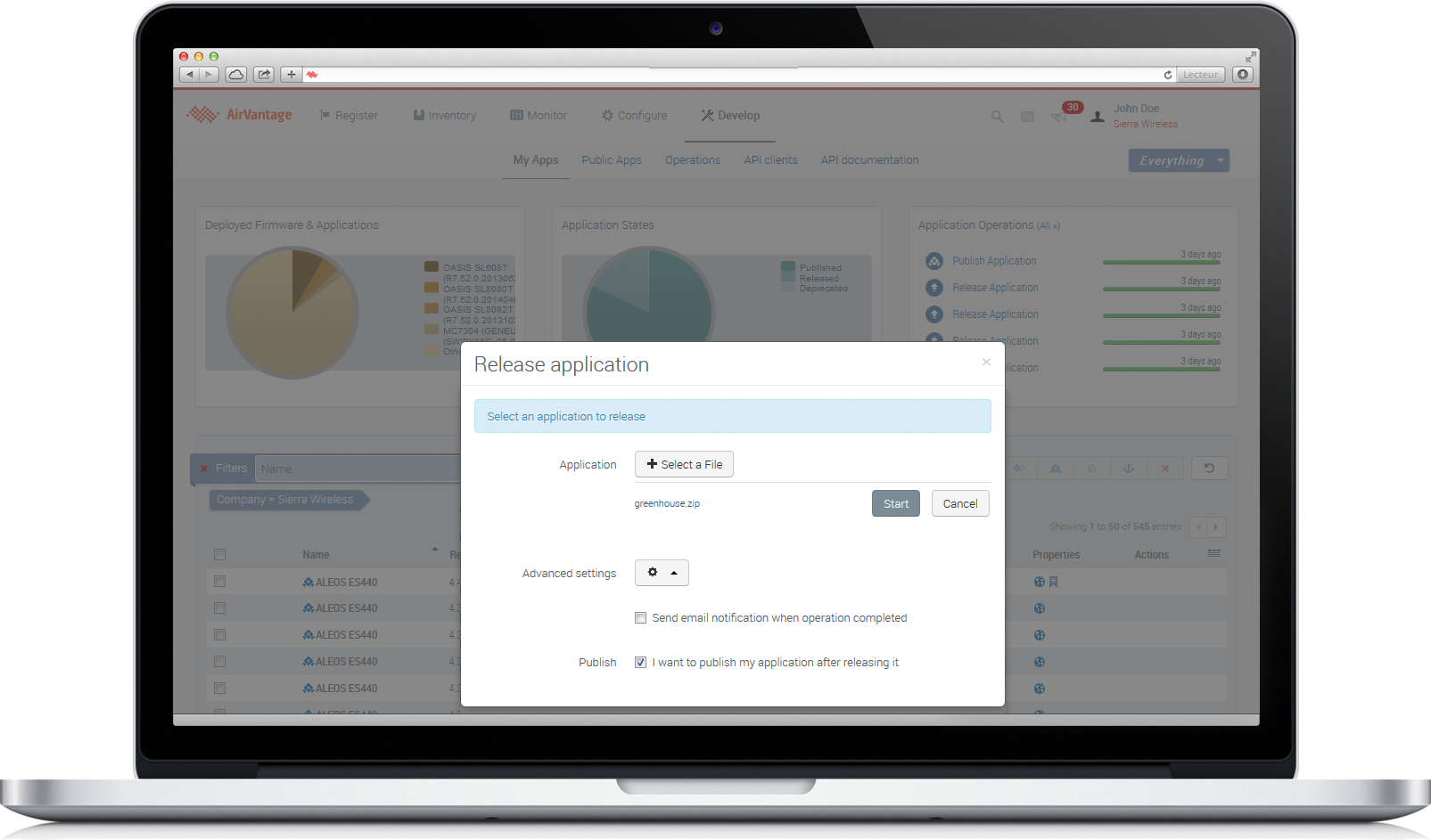
Release your application
- Select your file model.app.zip
- Open Advanced settings and select I want to publish my application after releasing it
- Finally, click on Start
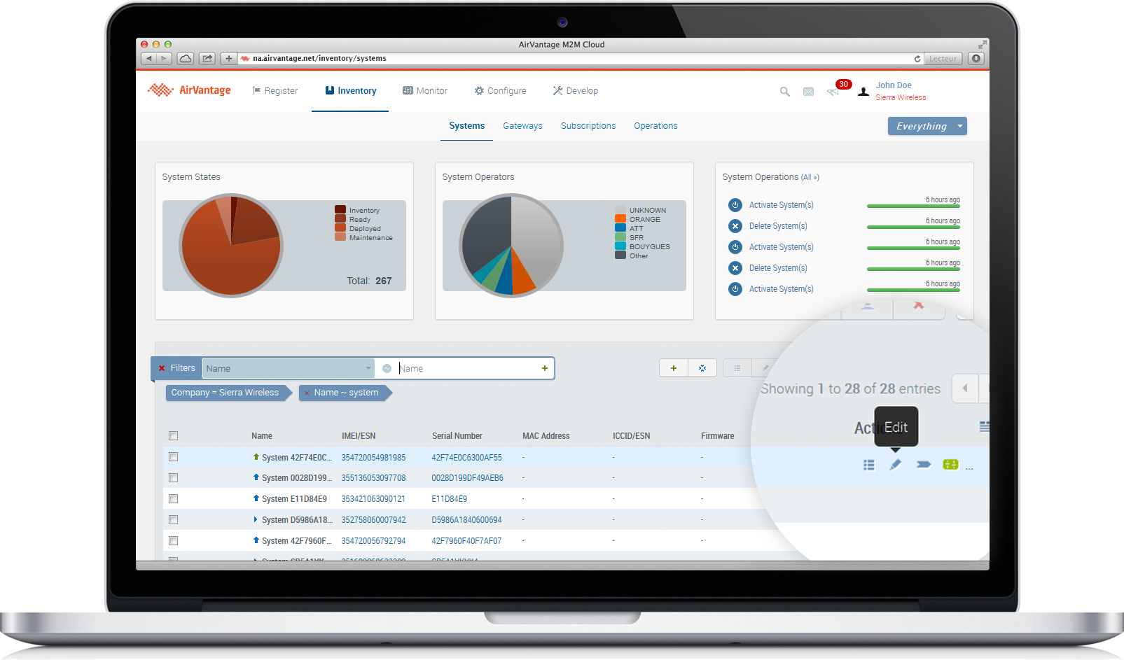
Edit your system
- Go on Monitor > Systems
- Select your system and click on Edit in the More menu
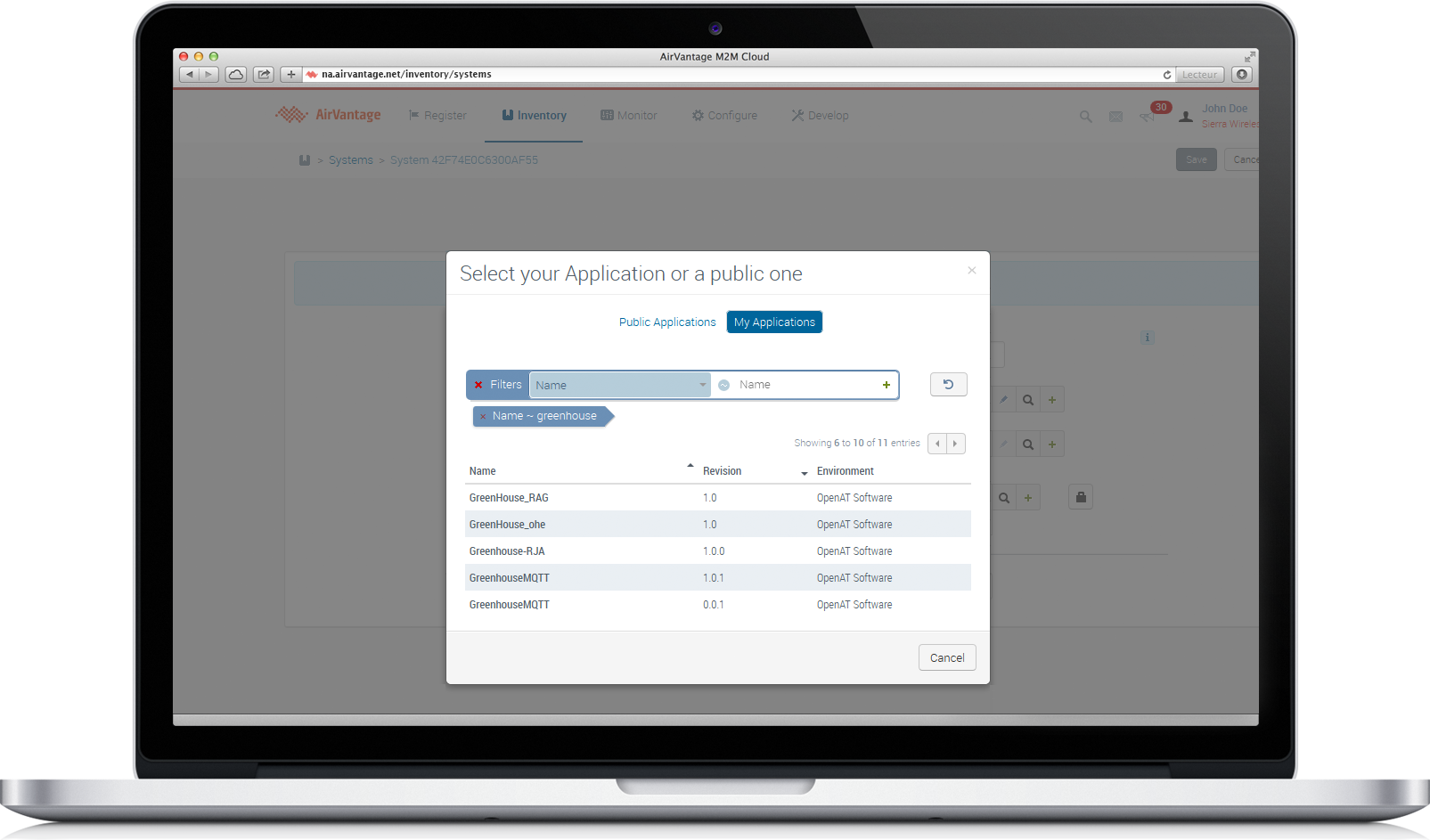
Search your application
- Click on Search application
- In the new dialog box, select the My Application tab
- Search your application using its name (AirVantage Greenhouse)
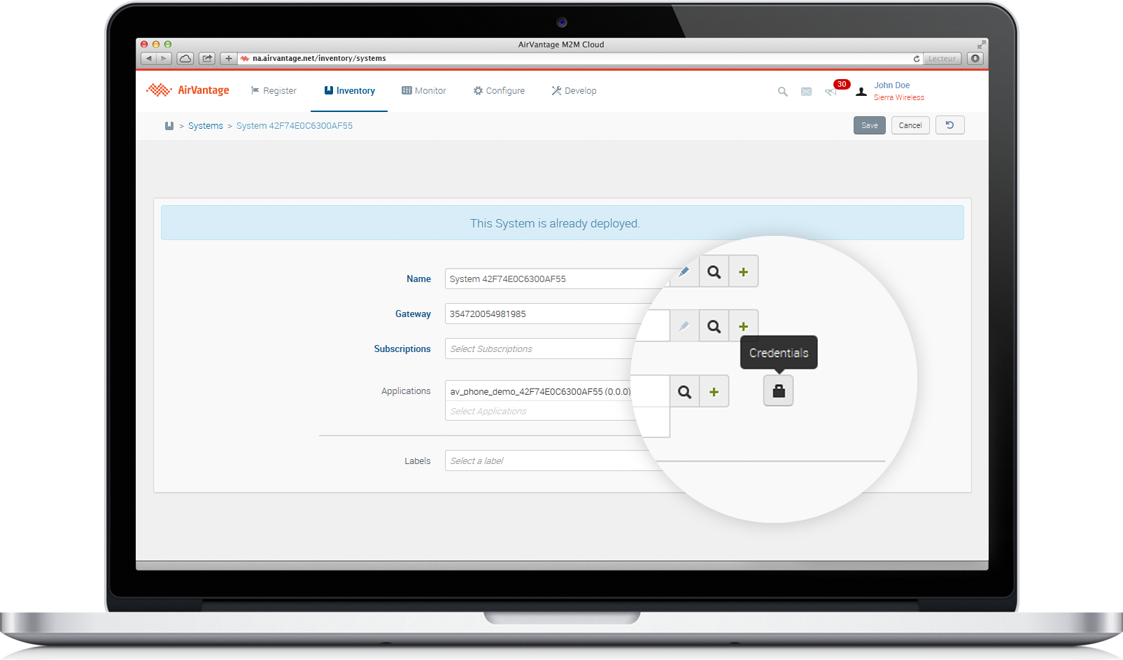
Associate your application to your system
- Click on the application to select it.
- Click on the padlock and configure the password.
- Click on Save in the right top corner
- Click on the Monitor icon to monitor your system
Step 3: Implementing an application
It is now time to write an application for the ST Nucleo. You can have a look about using MQTT in AirVantage, if you want to have a description about the serialisation details.
This C sample shows how to use MQTT to communicate with AirVantage.
The software architecture
To serialize the MQTT messages, we used the embedded Paho library.
We have added a higher level layer to supply API to manage the MQTT connection which implements each MQTT message.
We hadn’t implemented the SUSCRIBE, UNSUSCRIBE because it is not required by the AirVantage server and the DISCONNECTED message as well.
Finally, the application initializes the uart and declares a callback to receive the commands sent from AirVantage and it publishes the data by using the MQTT client layer.

Here a more details information about how to use the MQTT client API and how to configure the UART used to communicate with the HL.
The Application
The application configure the uart and loop to send data.
1) Declare and Configure a Serial object
//------------------------------------
// Hyperterminal configuration
// 115200 bauds, 8-bit data, no parity
//------------------------------------
Serial pc(SERIAL_TX, SERIAL_RX);
pc.baud(115200);
2) Start the MQTT Client
MQTTClient client(server, &callback, password, port, &pc, apn);

while(1)
    {
      if(client.connected == true)
      {
        ...
        client.pub ("home.alarm_threshold", "3.65");
        ...

      }
  };
The MQTT Client
Initialization
The initial declaration of the callback has been done here:
MQTTClient client(server, &callback, password, port, &pc, apn);
The MQTT client can now use the uart to analyze the byte received from the connection.
The callback function here will be used to received the notification when a new command will be received.
1) Attach a callback
// Setup a serial interrupt function to receive data
pc.attach(this,&MQTTClient::Rx_interrupt, Serial::RxIrq);
2) Implement a callback
This callback extracts the MQTT message from the bytes received from the HL.
// Interupt Routine to read in data from serial port
void MQTTClient::Rx_interrupt()
{
// Loop just in case more than one character is in UART's receive FIFO buffer
   while ((pc.readable()) )
   {
     rx_buffer[rx_in] = pc.getc();
     rx_in = (rx_in + 1) % BUFFER_SIZE;
    }
    return;
}
How the MQTT Client deals with MQTT messages
With the HL module, you have to program your software sequentially (i.e. each task must be completed before dealing with the next one).
You can’t do threaded programming to manage the HL.
You need to wait the response of each AT command to do the next task.
The MQTT client is designed basically as follow:
1) Connect
The function MQTTClient::connect follow the pattern of the TCP connection.
You can see those steps in the tutorial How to send data to AirVantage with the HL shield in standalone .
The embedded application is launched only after having received a CONNACK message from AirVantage (with or without any error).
2) Publish
The function MQTTClient::pub has been designed for one value or four values to be send in the same time.
The generation of the JSON payload is very simplified.
The JSON format is:
{"machine.temperature": 23.2, "machine.humidity": 70}
3) Ping
The function is called every 30 seconds to keep alive the connection.
4) Receive
The function MQTTClient::recvData is called every time in the loop. It checks if a command has been received.
Firstly, it checks if one byte or more has been received. Then, it decodes it to know the type of the message.
When it receives the rest of the message, it decodes the size and parses the full message.
Once the full message has been received, it extract from the AT command result the full MQTT message and supply the payload to the callback.
Finally, when a PUBLISH message has been received, it calls a callback function in main.cpp to decode it and then changes to the mode wanted by the users.
5) Decode Data
This function is used to decode the message received by the HL from the server. It can be a CONNACK, a PING_RESP or a PUBLISH message.

How MQTT client communicates with HL Shield
The MQTT Client communicates with HL Shield using the AT Commands. By this way, no IP Stack is required from the host processor.
1) Check if the SIM card is well inserted
Command:
AT+CPIN?
Response expected:
+CPIN: READY
OK
2) Configure the APN
Command for HL8
AT+KCNXCFG=1,“GPRS”,” internet.maingate.se”,“”,“”,IPV4,“0.0.0.0”
Command for HL6
AT+KCNXCFG =0,“GPRS”,“internet.maingate.se”,“”,“”,“0.0.0.0”
Response expected:
OK
3) Configure the address of the server
Command:
AT+KTCPCFG=1,0,” eu.airvantage.net”,1883
Response expected:
+KTCPCFG: 1
OK
4) Launch a TCP connection
Command:
AT+KTCPCNX=1
Response expected:
OK
5) Send data with the size of the payload
At the end of each payload, it must be finished with ‘\r\n\r\n’. It means that the size of the data send is size of the payload + size of ‘\r\n\r\n’ (i.e. 8 bytes). For a payload of 55 bytes we must send 63 bytes. 55 + 8 = 63 bytes.
Command:
AT+KTCPSND=1,63
Response expected:
CONNECT
[55 bytes of data….]\r\n\r\n–EOF–Pattern–
OK
6) The transmission is finished when the application sends this pattern –EOF–Pattern—
7) Receive data, the application is informed by a notification from the HL
+KTCP_DATA: 1,137
It means that 137 bytes has been received. To retrieve the data: Command:
AT+KTCPRCV=1,137
Response expected:
CONNECT
359515050152440/tasks/json[{“uid”:“49764eed1ef44817a8de410364f1244b”,“timestamp”:1434108462789,“command”:{“id”:“modeon”,“params”:{}}}]–EOF–Pattern–
OK
8) Close the TCP connection
Command:
AT+KTCPCLOSE=1,1
Response expected:
OK
9) Delete the configuration
Command:
AT+KTCPDEL=1
Response expected:
OK
View your application running
Your data is now sent. You can check your data communication. Just go to Inventory > Systems, then pick your own and click Timeline. That is it.
If you want to try it, it is all available on GitHub .
Next Step
Continue the tutorial by using tools supplied by AirVantage to test your communication with your device.