Configuring Wi-Fi
This page shows you how to configure Wi-Fi for your AirLink RX55 router in Access Point mode and Client mode.
 Initializing Table Of Contents...
Wi-Fi Interfaces
The following Wi-Fi Interfaces are available:
- Wi-Fi A
- Wi-Fi B
Each interface is configurable as Access Point (2.4GHZ or 5GHz) or Client (2.4GHz, 5GHz, or 2.4GHz + 5GHz).

Vehicle applications often require that the router provide Wi-Fi interfaces in both Access Point mode and Client mode.
For example:
- The router will provide a Wi-Fi Access Point (using the cellular WAN) in the vehicle for laptops and other client devices.
- The router will also provide a Client mode interface for when the vehicle enters a depot, where the router can connect to another Wi-Fi network (instead of the cellular WAN). The in-vehicle devices can then take advantage of the Wi-Fi WAN network (for example, to upload video camera or vehicle data to the depot network.)
Configuring a Wi-Fi Access Point
To configure an interface as an Access Point, click  at the end of a row for Wi-Fi A or Wi-Fi B in the WI-FI INTERFACES table (as shown above).
The Edit Wi-Fi Interface menu appears — configure the fields in any order.
- ENABLE the interface.
- Select the BAND the Access Point will use — 2.4GHz or 5GHz
- Select the MODE — Access Point in this case.
Select the LAN SEGMENT that you’re going to use for this access point.
Tip: Click X to display the list of available LAN segments. LAN segments are configured under Bridges (Networking > Zones Settings > Bridges).
Best Practice recommendation: If 2.4GHz and 5GHz APs are configured on different LAN segments, use different SSIDs and security passphrases to make sure DHCP renews IP adresses when switching between the APs.
Enter the access point’s SSID (a case-sensitive network name).
Select the SECURITY MODE — Depending on the mode selected, specific security credential types are required:
- OPEN — No security. (This mode is not recommended.)
- WPA — This option appears only when LEGACY MODE is enabled. Requires only a SECURITY PASSPHRASE. (This mode is not recommended.)
- WPA2 — Requires a SECURITY PASSPHRASE, plus 802.11w options.
- WPA2/WPA3 Transition Mode — Requires a SECURITY PASSPHRASE, plus automatically sets 802.11w internally as Optional.
- WPA3 — Requires only a SECURITY PASSPHRASE, plus automatically sets 802.11w internally as Required.
- WPA2-Enterprise — Requires operation; clients that do not support 802.11w will not connect.
Note: The 802.11w options do not appear for WPA3 or WPA2/WPA3 Transition Mode. For WPA2/WPA3 Transition Mode, ‘Optional’ is automatically used. For WPA3, ‘Required’ is automatically used.
For WPA2-Enterprise security mode only:
- Select the RADIUS AUTHENTICATION SERVER to use.
- Select the RADIUS ACCOUNTING SERVER to use. Note: RADIUS servers must use IPv4 addresses. FQDNs and IPv6 addresses are not supported.
Set LEGACY MODE — When enabled, Legacy Mode restores security option WPA (version 1) in the SECURITY MODE list, and supports TKIP encryption for WPA/WPA2 modes. When disabled, only AES encryption is supported.
Enable AUTO-CHANNEL to have the router choose the channel on which to operate.
To use a specific channel, disable AUTO-CHANNEL and then select a channel from the CHANNEL list that appears.Enable DFS CHANNELS to open up more Wi-Fi channels for the router to use, while preventing the router interfering with channels used by radar equipment (near airports, for example). With DFS CHANNELS enabled, the router will switch channels if it detects radar equipment using the same channel. Unless you know that your operating equipment is DFS capable, Sierra Wireless recommends leaving DFS CHANNELS disabled.
Enabling DFS allows for more 5GHz channels, but may result in delayed connectivity at boot and in the presence of radar.

- Set the BEACON INTERVAL to configure how often the router sends periodic messages (beacons) to advertise its availability. 100 milliseconds is the default setting.
- Set the DTIM PERIOD to the number of beacons (plus 1) that a client device can sleep through before waking to check for messages.
For example, if the DTIM Period is set to 3, the client sleeps through two beacons and wakes for the third beacon. The higher DTIM PERIOD value, the longer the client device can sleep, and the more battery power the client device can potentially save. However, high DTIM periods can also reduce throughput to the client. The default period is 2 (wake for every second beacon). - Enable BROADCAST SSID to have the router make the SSID visible to client devices. If BROADCAST SSID is disabled, the SSID is not shown to other devices, and the SSID and passphrase must be entered on the client for a client to connect.
When CLIENT ISOLATION is disabled (the default setting), clients can “see” each other, and potentially sniff traffic from each other.
- For passenger Wi-Fi applications, enable client isolation to enhance security.
- Disable client isolation if you have client applications on the same LAN segment that need to interact with each other.
Set the MAX NUMBER OF CLIENTS — Enter the maximum number of clients that can connect simultaneously to this access point interface. As a guideline, set a limit that is slightly higher than the number of clients you expect to connect. The default is 10, with a range of 1 to 10.
Set MSS CLAMPING — MSS (Maximum TCP Segment Size) Clamping controls the maximum packet size used for TCP connections between a local (LAN-side) host and a remote host over the Wi-Fi WAN interface. MSS Clamping helps avoid possible issues with sending and receiving large TCP packets over the cellular network when other standard MTU mechanisms do not appear to be working with your installation. The options are:
- Disabled (default)
- Auto — MSS is clamped at 40 bytes (20 byte IP header + 20 byte TCP header) less than the MTU of the Wi-Fi interface.
- Manual — MSS is clamped to the specified maximum value bi-directionally for all inbound (remote-to-LAN) and outbound (LAN-to-remote) TCP connections when the TCP session is established using the Wi-Fi interface.
MSS — When MSS CLAMPING is set to Manual, set the Maximum TCP Segment Size.
- Range is 1–2000 bytes (default is 1460)
Managing APs During Client Association
A DISABLE APS ON CLIENT ASSOCIATION switch is below the WI-FI INTERFACES table.
This switch is disabled by default.
If this switch is enabled, the router will automatically disable some or all of its Access Points and Additional SSIDs when its Wi-Fi Client connects to a Wi-Fi access point (for example, when arriving at a service vehicle depot). Then, when the router disconnects from the access point, its own Access Points and Additional SSIDs are automatically re-enabled.
To configure this feature:
- Enable the switch. Configuration fields appear.
- Set the DISABLE AP DELAY to the length of time to wait before disabling the router’s Access Points. If no delay is required, set the delay to 0.
- Optionally, choose from the DISABLE AP IGNORE LIST any APs and Additional SSIDs that should not be disabled by this feature.

Monitoring Access Point Mode Operation
On Status/Monitoring > Dashboard, the LAN dashboard shows you the Wi-Fi LAN interfaces and the LAN segments they use. A blue Access Point icon (![]() ) indicates the interface is enabled and operating.
) indicates the interface is enabled and operating.
Tip: Click a Wi-Fi LAN interface icon to go to the WI-FI INTERFACES configuration table and review your configuration. Hover your cursor over the DATA USAGE pie chart segments to see usage for each connection type.

Additionally, you can go to Status/Monitoring > System > Wi-Fi to view detailed Wi-Fi Access Point status, including the active channel and connected stations (clients).

Configuring Wi-Fi Client Mode
You can create a Client Mode configuration by using a scanned SSID from the SSID Database, or by creating an SSID. The router will use the SSID for its WAN connection.
When connecting the router to an internal network via Wi-Fi or Ethernet WAN, ensure that the network providing a WAN link does not use the router’s default internal subnet (192.168.1.0/24). The address conflict will prevent the WAN connection from being established.
For more information, see this Sierra Wireless Customer Community article.

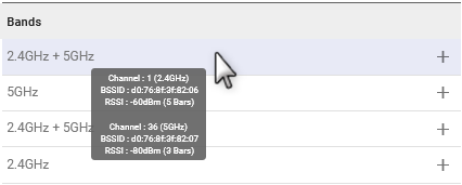
Tip: Rest the pointer on an SSID to view the channel, BSSID and RSSI for each band.
To use a scanned SSID:
- In the SCANNED SSIDS table, click + to add the desired SSID to the SELECTED SSIDS table. You must then fully enable the new SSID by adding the SSID’s security passphrase.
- In the SELECTED SSIDS table, click
 (Edit) for the desired Client SSID.
 - In the Edit SSID screen, add the security passphrase and assign a priority (optional).
- Click UPDATE.
 (Edit) for the desired Client SSID.
After you configure the SSID with a passphrase, the Wi-Fi Client interface starts using it (if another SSID with a higher priority is not configured).

To create an SSID manually:
- Under the SELECTED SSIDS table, click CREATE SSID.
- In the Create SSID screen, enter the SSID name.
- Select a SECURITY MODE. For mode WPA2 or WPA2 Enterprise, 802.11w options appear. If required, select an option to enable 802.11w operation. The 802.11w standard uses Security Association Query Requests to ensure that clients are legitimate. Options are:
- Disabled
- Optional (default): 802.11w will be used when connecting to access points that support it.
- Required: forces 802.11w operation; the router will not connect to access points unless they have 802.11w enabled. For WPA2/WPA3 Transition mode access points, Optional is used automatically. For WPA3-only access points, Required is used automatically.
- Select the PRIORITY. The smaller the value, the higher the priority. Leaving PRIORITY blank puts this SSID at the lowest priority.
- Click CREATE.

Additional Client mode configuration
You can complete or edit the Client mode configuration in the WI-FI INTERFACES table.

To configure an interface as a Client, click
at the end of the row of a Client interface.
The Edit Wi-Fi Interface menu appears — configure the fields in any order.
- ENABLE the interface
- Select the BAND — 5GHz, 2.4GHz, or 2.4GHz + 5GHz
Leave the MODE as Client.
Set the SSID SELECTION switch:
When you have multiple SSIDs configured, Sierra Wireless recommends leaving SSID SELECTION at the default Auto (Highest Priority) setting. The router will automatically search and connect to an SSID depending on priority. If priorities are identical, the router will use the closest SSID with the fastest estimated link speed. To configure the Wi-Fi client to use only a single, specific SSID, set SSID Selection to “Manual” and then choose the CONFIGURED SSID you wish to connect to.
- Enable DFS CHANNELS to open up more Wi-Fi channels for the router to use, while preventing the router interfering with channels used by radar equipment (near airports, for example). With DFS CHANNELS enabled, the router will switch channels if it detects radar equipment using the same channel. Unless you know that your operating equipment is DFS capable, Sierra Wireless recommends leaving DFS CHANNELS disabled.
Enabling DFS allows for more 5GHz channels, but may result in delayed connectivity at boot and in the presence of radar.
- Enter the SCAN INTERVAL, which sets how often the router scans for SSIDs when disconnected.
- Set MSS CLAMPING — MSS (Maximum TCP Segment Size) Clamping controls the maximum packet size used for TCP connections between a local (LAN-side) host and a remote host over the Wi-Fi WAN interface. MSS Clamping helps avoid possible issues with sending and receiving large TCP packets over the cellular network when other standard MTU mechanisms do not appear to be working with your installation. The options are:
- Disabled (default)
- Auto — MSS is clamped at 40 bytes (20 byte IP header + 20 byte TCP header) less than the MTU of the Wi-Fi interface.
- Manual — MSS is clamped to the specified maximum value bi-directionally for all inbound (remote-to-LAN) and outbound (LAN-to-remote) TCP connections when the TCP session is established using the Wi-Fi interface.
- MSS — When MSS CLAMPING is set to Manual, set the Maximum TCP Segment Size.
- Range is 1–2000 bytes (default is 1460)

Monitoring Client Mode Operation
On Status/Monitoring > Dashboard, the WAN dashboard shows you the Wi-Fi WAN interfaces. A grey Wi-Fi icon (![]() ) indicates a disconnected interface. A blue Wi-Fi icon (
) indicates a disconnected interface. A blue Wi-Fi icon (![]() ) indicates a connected interface.
) indicates a connected interface.
Tip: Click a Wi-Fi icon to go to the WI-FI INTERFACES configuration table and review your configuration.

Additionally, you can go to Status/Monitoring > System > Wi-Fi to view detailed Wi-Fi Client status, including bitrate and the active channel.
