 Searching...
Telemetry Tab
Introduction
Telemetry provides automotive self-diagnosis and reporting. Telemetry interfaces with a vehicle using the standard OBD-II protocol. OBD (On-Board Diagnostics) is the electronic interface system of compliant automobiles. OBD-II is an updated OBD standard which is mandatory for cars sold in the US after 1996.
Telemetry can also monitors a number of Parameter IDs (PIDs)/Suspect Parameter Numbers (SPN) specific to heavy duty commercial trucks via an HDODB (Heavy Duty Onboard Diagnostics) port.
Through OBD-II, Telemetry gains real-time access to diagnostic data generated by various electronic systems embedded within a vehicle.

Note: Telemetry does not support fault clearing (e.g., reset the check engine light) when faults are found, and the availability of diagnostic data may be limited by the make and year of the vehicle.
Telemetry requires an OBD-II compliant scan tool to read the diagnostic data from the vehicle and this tool is provided by Sierra Wireless. Telemetry sends the vehicle data to an MG or MP70 gateway connected to the scan tool. The gateway then passes this data to the AMM where it can be used to generate reports such as driver behavior, fuel consumption, and vehicle diagnostics. Note that MP70 gateways can only receive a subset of the Telemetry data that MG routers can receive.
Note: MP70 gateways require data streaming and AVTC in order to access the data (both of these are described below in Configuring Telemetry for an MP70). MG routers must be configured with the Telemetry module in order to access the data.
For more information about OBD-II, please refer to: http://en.wikipedia.org/wiki/On_Board_Diagnostics.
This topic covers all topics related to the installation, configuration and usage of Telemetry and is intended to be used by the following audiences:
- Hardware and Vehicle Installers should read the following sections:
- Telemetry Verification Kit: describes the kit used to verify which vehicle parameters can be read by Telemetry for a particular vehicle.
- Telemetry Hardware: describes the hardware and installation process.
- System Administrators should read: Configuring Telemetry for an MP70, Configuring Telemetry on an MG router for Light-duty Vehicles, Configuring HD Telemetry on an MG router for Heavy-duty Vehicles which describe how to configure telemetry on gateways and the AMM, and how to set up user accounts and thresholds so that telemetry information is available to fleet operators.
- Fleet Operators should read Operation, which describes how to view telemetry information.
It is assumed that the reader has access to the appropriate account and password on the gateway and AMM to configure telemetry.
Telemetry is designed for fleet managers, service managers and technicians, human resource managers, and other personnel who manage fleets, fleet personnel and associated data.
Telemetry is applicable to vehicles equipped with Onboard Diagnostics Version 2 (OBD-II) data bus connections, which are typically light truck and passenger vehicles.
Telemetry information may be limited to specific makes and models of vehicles. For more information contact your vehicle’s manufacturer or Sierra Wireless sales representative.
Theory of Operation
Telemetry has three main operations:
OBD-II Data Collection Through a Gateway
An gateway collects OBD-II data in real-time from the OBD-II scan tool that it is connected to. There is a wide range of information which can be collected including vehicle speed, engine temperature and battery voltage.
The gateway stores the returned OBD-II data and forwards it to the AMM for viewing purposes. The gateway can store ODB-II data for up to a few days when WAN connectivity is not available and will forward the data once the connection is reestablished. Note that the amount of data which can be stored depends on your configuration.
For a complete list of data monitored by telemetry, see Telemetry Parameters and Summary of HD Telemetry PID/SPNS.
OBD-II Data Viewing via the AMM Dashboard
OBD-II data is available for viewing on the AMM. This requires a special Telemetry management module to be activated on the AMM. This module includes a dashboard, stats, events, and a map view as well as specialized Telemetry Reports and Thresholds.
For more information see Configuring Telemetry for an MP70, Configuring Telemetry on an MG router for Light-duty Vehicles, and Configuring HD Telemetry on an MG router for Heavy-duty Vehicles.
For more information about using Telemetry and viewing data, see Operation.
OBD-II Data Alerting and Reporting via the AMM
The AMM can generate reports and send out alerts to specified users based on defined thresholds on the OBD-II data.
For more information about setting up Telemetry Thresholds, see AMM Thresholds Setup.
For more information about Telemetry reports see Telemetry Reports.
Telemetry Verification Kit
Sierra Wireless provides a telemetry verification kit that can be used to check if a vehicle will be compatible with the Telemetry application installed on a gateway.
This kit enables a laptop running special verification software (included in the kit) to check which OBD-II PID’s are being output by the vehicle’s onboard computer, therefore indicating which parameters a gateway will be able to report on for that vehicle.
The verification kit includes the following components:
Components for Light-Duty Vehicles
- OBD-II diagnostic cable: connects to the vehicle OBD-II socket and one side of the OBD-II scan tool.

Scanner and Cables
- Scanner.
- Scanner-to-serial port cable: cable for connecting between the serial port on the scanner and the serial port on the laptop.
- USB-to-serial converter cable: optional cable for USB connectivity between the scanner and a USB port on the laptop.
- USB stick: contains the self-booting software utility to be run on a laptop which is used for verifying compatibility.
Components for Heavy-Duty Vehicles
- Heavy-duty diagnostic cable: connects to the vehicle’s Deutsch socket and one side of the scan tool.

HD Scanner and Cables
- AutoTap Scanner.
- Scanner-to-serial port cable: cable for connecting between the serial port on the scanner and the serial port on the laptop.
- USB-to-serial converter cable: optional cable for USB connectivity between the scanner and a USB port on the laptop.
- USB stick: contains the self-booting software utility to be run on a laptop which is used for verifying compatibility.
Before Running
Follow these steps Before Running:
Connect the scanner to the laptop as follows:
- Plug the male end of the scanner-to-serial port cable into the scanner. Do not plug the other end into the laptop at this point.
- (Optional) For USB connectivity, plug the serial end of the USB-to-serial converter cable into the scanner-to-serial port cable. This will enable a laptop to communicate using USB instead of serial.
- Connect the vehicle to the scanner:
- Light-duty vehicles: Plug the serial end of the OBD-to-serial cable into the other end of the scanner. Do not plug in the OBD end of the cable into the vehicle at this point.
- Heavy-duty vehicles: Plug the serial end of the Deutsch-to-serial cable into the other end of the AutoTap scanner. Do not plug in the Deutsch end of the cable into the vehicle at this point.
Note: This topic assumes that the you have a laptop on which you can access the BIOS.
Running the Verification Kit Utility
Insert the USB stick from the Telemetry Verification Kit into a free USB port on the laptop, and proceed to boot the laptop from the USB stick.
Note: if your laptop does not boot from a USB stick, you will need to access your laptop’s BIOS settings and modify them to enable booting from USB.
Upon successfully booting the verification kit utility from the USB stick, proceed through the appropriate set of steps below:
Running the Verification Kit Utility for Light-Duty Vehicles
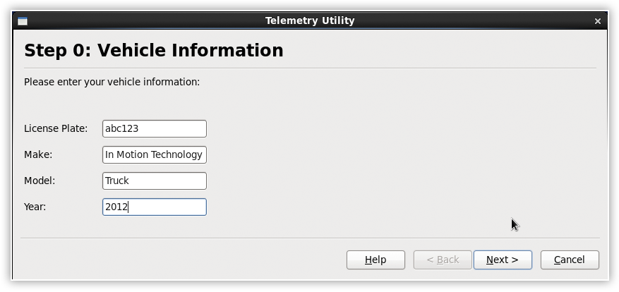
- Input the vehicle information and click Next:
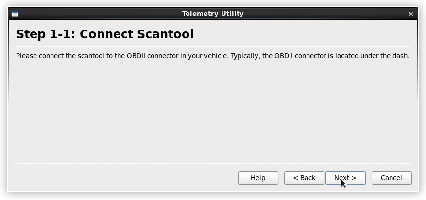
- Connect the OBD end of your serial-to-OBD cable to the vehicle and click Next on the Scantool page:
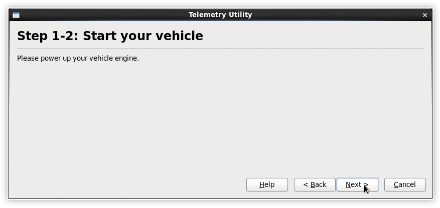
- Start the vehicle when prompted and click Next:
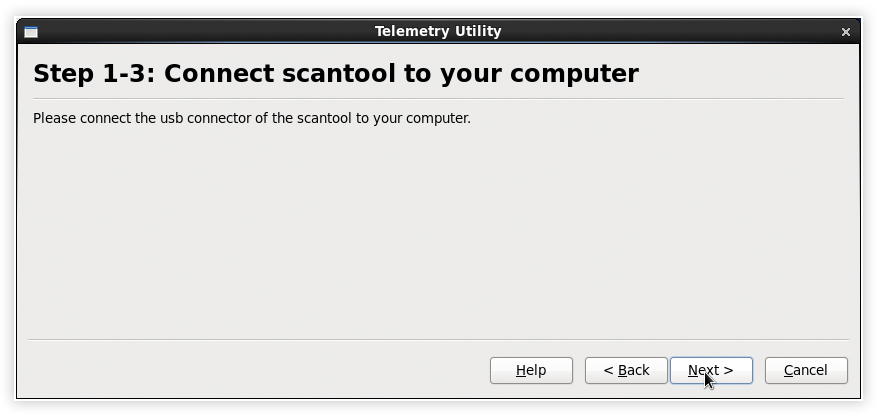
- Connect the serial or USB end of the cable from the scanner to the computer on the Scantool page and click Next.
- Select the USB port where the scanner is connected to and click Next. Alternatively, if using a serial cable, select Customize device path and enter the gateway’s path (e.g.
/dev/ttyS0):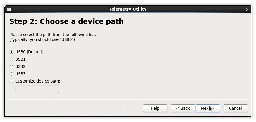
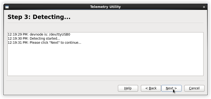
- The compatibility check process will run:
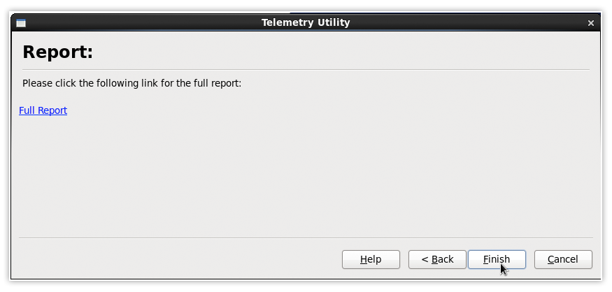
The final report is saved in
/Desktopon the USB stick in HTML format. Each time the utility is run, a new entry is added to the files, allowing for information from an entire fleet to be saved and reloaded. - To view the report click Full Report, or click on Finish to exit:


The report is displayed:

Note: if a vehicle parameter is shown as “Not Found” in the report, this means that the vehicle does not support it and it will not be available to the AMM.
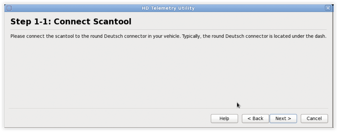
Running the Verification Kit Utility for Heavy-Duty Vehicles
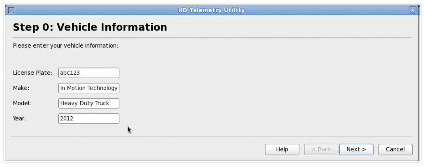
- Input the vehicle information and click Next:
- Connect the OBD end of your serial-to-OBD cable to the vehicle and click Next on the Scantool page:
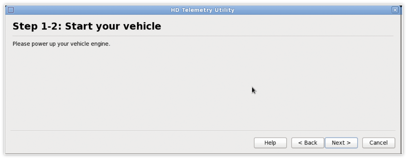
- Start the vehicle when prompted and click Next:
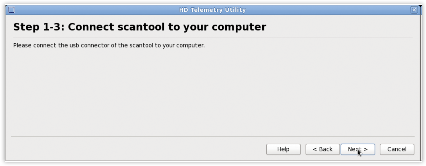
- Connect the serial or USB end of the cable from the scanner to the computer on the Scantool page and click Next.
- Select the USB port where the scanner is connected to and click Next. Alternatively, if using a serial cable, select Customize device path and enter the gateway’s path (e.g.
/dev/ttyS0):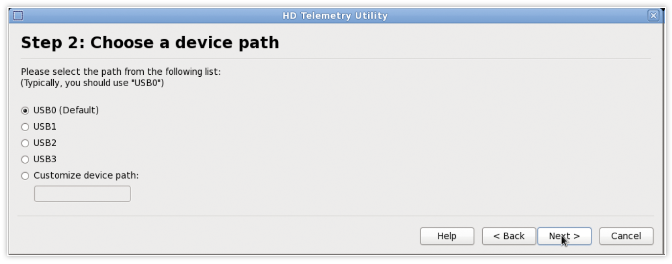
- The compatibility check process will run:
The final report is saved in
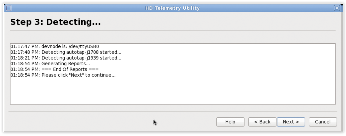
/Desktopon the USB stick in HTML format. Each time the utility is run, a new entry is added to the files, allowing for information from an entire fleet to be saved and reloaded. - To view the report click on Full Report, or click Finish to exit:
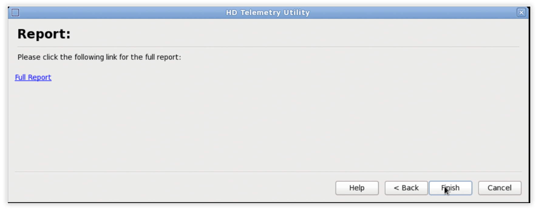


The report is displayed:

*Note: if a PID is shown as “Not Found” in the report, it means the vehicle does not support the PID and therefore it will not be available to the AMM.
Telemetry Hardware
Telemetry uses data from the vehicle diagnostic bus (OBDII) which is obtained via a scanner. The scanner must be purchased from Sierra Wireless and comes with the additional components described below. The part numbers for this kit are:
- Light-duty Vehicles: IMTMIS010.
- Heavy-duty Vehicles: IMTMIS070 (6-pin) or IMTMIS071 (9-pin).
The following Sierra Wireless hardware components are required to enable and use telemetry on a gateway:
- An MP70 with a minimum software release of 4.12.0 or, an MG router with a minimum software release of 2.8.5 or greater is recommended.
- Scan tool kit (supplied by Sierra Wireless) which includes:
- Light-duty Vehicle: 15’ OBD cable that connects the scan tool to the vehicle OBD port.
- Heavy-duty Vehicle: 25’ OBD cable that connects scan tool to vehicle HDOBD port (there are two formats for this connector: 6-pin and 9-pin. Check with your vehicle manufacturer prior to ordering from Sierra Wireless).
- Telemetry scan tool.
- Custom 10’ RS232 cable (containing female DB9 connectors on both ends) that connects the scan tool to the gateway.
This section assumes that the gateway is properly installed and configured with a network service card. Refer to the appropriate hardware guide for the gateway for more information on configuration. Hardware guides and other resources for currently supported gateways can be found using the following links:
The installer is expected to be familiar with the location of the OBD-II or Deutsch connector in the vehicle.
1 Power on the gateway, and verify it can connect to a WAN service (a steady green light should show)
2 Verify that the gateway meets the software requirements for telemetry. In the event that the gateway requires a new version, please contact Support to schedule an over-the-air software upgrade
Note: you must have a valid support plan in place in order to receive this upgrade.
3 Locate the OBD-II or Deutsch port in the vehicle. The port is an electrical socket most commonly located under the vehicle dashboard on the driver’s side near the center console
4 Install the Sierra Wireless-supplied scan tool:
- Light-duty vehicles: Attach the male SAE J1962 16-pin connector of the scan tool to the vehicle’s OBD-II port on the light-duty vehicle. SAE J1962 is the technical name for OBD-II connectors.
- Heavy-duty vehicles: Attach the Deutsch connector to the vehicle’s Deutsch port and the other end of the cable to the scanner.
5 Depending on the particular vehicle, you may wish to tie-wrap the cable in place to ensure the cable and scan tool do not disconnect as a result of vibration during subsequent operations.
6 Attach the Sierra Wireless-provided custom serial cable connecting the male serial connector of the scan tool, and the serial connector of the gateway.

Configuring Telemetry for an MP70
Configuring Telemetry for an MP70
Follow the steps below to configure Telemetry for an MP70:
- Configure data streaming for the gateway as described here .
- Install AVTC on the gateway to allow for transmission of proprietary data as described in the AirLink Vehicle Telemetry Configuration Application.
- The scanner can be connected directly to the serial port or into a USB port (requires a USB-to-Serial adaptor).
Configuring Telemetry for MG routers
Configuration is required on both the MG router and AMM in order collect telemetry data and present it to the user. The following subsections assume the reader is familiar with using the AMM and accessing an MG router through the web interface.
Configuring Telemetry on an MG router for Light-duty Vehicles
Use the following steps to enable Telemetry on an MG router:
1 Connect to the MG router’s LAN. In a web browser, go to http://welcome.to.inmotion/MG-LCI and log in as administrator.
2 Navigate to Devices > Serial, use the drop down menu to select Application from the default SerialConsole. This will allow the rear panel serial port to be used for communication with the scan tool.
3 Navigate to Applications > Telemetry.
Note: if the Telemetry Configuration tab is not available, then the Telemetry Application has not been installed on the gateway. If this is the case, call Support to request a software upgrade.
4 Under Master Options, check Enable and click on Submit. This configures the OBD-II agent service to run automatically whenever the gateway reboots.
5 Navigate to Telemetry > Telemetry Status to set the Odometer value.
a Under Odometer Reference Update, enter the current odometer value in the Current Odometer field. Note that the vehicle’s engine must be turned ON for this step. If required, this step can be completed at a later time.
b Select km or mi for the Current Odometer field’s units.
c Click Submit.
Note: when the vehicle is serviced, the Current Odometer value may need to be reconfigured.

6 The scanner can be connected directly to the serial port or into a USB port (requires a USB-to-Serial adaptor). If the default serial connector is not used, select the appropriate gateway from the list under OBDII Adapter Attachment.
The default PIDs should not be changed unless authorized by Sierra Wireless, as they represent the underlying Telemetry data reported to the AMM. For more information about changing these values, contact Support.

Configuring HD Telemetry on an MG router for Heavy-duty Vehicles
Use the following steps to enable telemetry on an MG router:
1 Connect to the gateway’s LAN. In a web browser, go to http://welcome.to.inmotion/MG-LCI and log in as administrator.
2 Navigate to Devices > Serial, use the drop down menu to select Application from the default SerialConsole. This will allow the rear panel serial port to be used for communication with the scan tool.
3 Navigate to Applications > HD Telemetry.
Note: if the Telemetry tab is not available, then the Telemetry Application has not been installed on the gateway. If this is the case, call Support to request a software upgrade.
4 Under Master Options, check Enable to activate the HD Telemetry application.

5 In most cases, setting the Scanner Type to AutoTap will work. However if your vehicle supports both J1708 and J1939 and you want to ensure that a specific protocol is used, select if from the list.
6 The scanner can be connected directly to the serial port or into a USB port (requires a USB-to-Serial adaptor). If the default serial connector is not used, select the appropriate gateway from the list under Adapter Attachment. The default PIDs should not be changed unless authorized by Sierra Wireless, as they represent the underlying Telemetry data reported to the AMM. For more information about changing these values, contact Support. Note that some vehicles may use the term SPN (Suspect Parameter Number) in place of PID.
7 Click Submit to save the configuration changes.

Telemetry thresholds corresponding to telemetry stats, are used for displaying alerts both on the Dashboard and Telemetry dashboard tabs.
Thresholds are usually created by Sierra Wireless during the provisioning stage of the AMM, but may need to be created by an AMM’s administrator. For more information about creating and configuring thresholds, see Thresholds .
Note: the availability of Telemetry Stats is based on whether those Stats have been reported by the gateway(s) associated with the AMM. Note: when operating on a hosted AMM, the available Stat types may include those not reported by your current fleet. This occurs because the hosted AMM software lists all Stats types available including those reported by other fleets.
For a complete list of items which can be reported as Stats, see Telemetry Parameters and Summary of HD Telemetry PID/SPNS.
Operation
After Telemetry has been properly configured, it should start automatically and operate continuously whenever the gateway is powered up.
The gateway’s Telemetry software will use its configuration settings to report changes to PID values to the AMM. The AMM will automatically receive data from all gateways having an appropriately configured Telemetry application.
Telemetry Data can be viewed in three areas on the AMM:
-
Dashboard Tab
The AMM’s Dashboard displays the configured Stats and Thresholds which include both those related to telemetry and as well as those defined for other measurable subsystems.
Dashboard with Telemetry Stats and Thresholds
Thresholds display alerts (warning, errors etc.) when a Stat’s value has exceeded a specified range. For example, the Dashboard shown above contains different colored Threshold bubbles for the CoolantTemp Telemetry Stat.
Telemetry Stats marked as N/A (not applicable) indicate that either the Stat cannot be reported by the vehicle or that it hasn’t been reported yet.
-
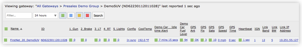
Telemetry Dashboard Tab
The Telemetry Dashboard tab displays the Telemetry Stats reported by a gateway or group of gateways selected in the AMM’s gateway tree. To show alerts including errors and warnings for a Stat, a Threshold must be defined corresponding to that Stat.
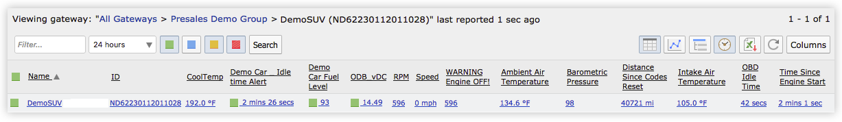
Telemetry Dashboard Tab
The availability of the columns on the Telemetry dashboard tab depends on:
- which telemetry Stats have been permitted for display for the current user (see User Accounts) and
- which Stats have been reported by a gateway or selected fleet of gateways.
For those gateways which have not reported a parameter, “N/A” (not applicable) will be shown in place of a parameter value. The values shown for each gateway represent the last values reported by those gateways. The frequency of updates is controlled by the Report When Value Changes By and the Report When Value Stable For options defined for each parameter on the gateway.
-
Telemetry Reports
The following telemetry reports provide high-level information about the data acquired from the vehicle:
Telemetry Reports Supported on MP70 Gateways:
- Driving Behavior : provides information about driving behaviors such as speed, idling, acceleration etc.
- Vehicle Hours : shows how long a vehicle has been running including both driving time and idle time.
- Odometer : reports the distance traveled over a specified time range.
Telemetry Reports Supported on MG routers:
- Driving Behavior : provides information about driving behaviors such as speed, idling, acceleration etc.
- Vehicle Hours : shows how long a vehicle has been running including both driving time and idle time.
- Fuel Fillup : displays data on the date/time, location and fuel fill-up amounts.
- Fuel Consumption : provides information about fuel consumption and efficiency based on runtime, fuel cost etc.
- Fuel Consumption Trend : summarizes fuel consumption over a period of time.
- Vehicle Diagnostics : reports on vehicle voltage, coolant and MIL.
- Odometer Check : compares the odometer value obtained from Telemetry data against that acquired from GPS data.
- Unauthorized Usage : provides information about vehicle usage based on a configurable set of operating parameters.
All Telemetry reports are accessed using the Reports > Telemetry menu.
For more information see Reports


Note: in the event that the scanner becomes disconnected or the OBD-II connector is defective, the AMM should report a Disconnected message. This may result in unexpectedly large amounts of information being stored in the AMM database related to the disconnection state, which may need to be periodically purged.
If operating on a hosted AMM, this procedure will be performed according to Sierra Wireless maintenance schedules and data retention policies. Note that you will not be able to control retention policies on the hosted service and you may want to acquire your own AMM appliance. Please contact Sales if you are interested in hosting your own AMM appliance.
Proprietary Vehicle Data
Using Airlink Vehicle Telemetry Configuration (AVTC) to read Proprietary Vehicle Data
AirLink Vehicle Telemetry Configuration (AVTC) is an AAF application that allows convenient distribution of proprietary vehicle configuration information to supported AirLink gateways.
AVTC consists only of vehicle-specific data. There is nothing to configure on the app itself. When installed on a supported AirLink gateway running ALEOS 4.12.0 or later, it enables the gateway to collect proprietary vehicle data parameters. AVTC enables reporting of proprietary vehicle information to the AMM (with AMMER installed).
Note: The AVTC app only applies to ALEOS routers that are directly connected to the vehicle bus (e.g., MP70).
For information on setting up AVTC via the AMM, see the AirLink Vehicle Telemetry Configuration Application.
Troubleshooting
Ensure that the HD Telemetry scanner is properly connected. If the scanner is not connected, the AMM should report that the scanner is disconnected.
If the scanner is not physically connected to the HDODB port or if the HDODB port on the vehicle is defective, the Telemetry panel will show 0 (zero) or N/A.
When the scanner is not connected or the engine is OFF, navigate to the Telemetry Status tab (for light-duty vehicles) or the Heavy Duty Telemetry status tab (for heavy-duty vehicles) in the LCI, to verify the state of the scanner. If the scanner is operating normally, the State field should indicate ACTIVE_SCAN as shown below. If the scanner is disconnected it should display INIT. If the scanner is connected but the engine is off it should display INVALID_ECU_CONNECTION. A disconnected message indicates that the scanner is not physically connected to the Deutsch port or the Deutsch port on the vehicle may be defective.

Scanner Disconnection Status in the LCI for Heavy-duty vehicle
When the odometer is set manually via the LCI, the odometer will increment based on the Distance since codes cleared PID. If the Distance since codes cleared PID is reset during maintenance of the vehicle or if the battery is removed, the odometer value may need to be re-entered via the LCI.
Some vehicles may not support all PIDs or may use a proprietary method that is not supported by Sierra Wireless. In such a case, the AMM Dashboard or Telemetry dashboard may not display this PID or may show N/A rather than a value. To check which ID’s are being reported by a vehicle, use the verification kit.
The following list describes the ODB-II light-vehicle vehicle parameters which can be reported as Telemetry Stats to the AMM. A full list of ODB-II PIDs is available at: http:// en.wikipedia.org/wiki/OBD-II_PIDs.
Note that some parameters may not be available on some vehicles. Also, the parameters are measured in metric units on the gateway, but can be reported in either metric or imperial units on the AMM depending on the measurement units selected in the AMM’s user preferences. If imperial is selected as the display unit on the AMM, then the AMM will automatically convert the values from metric.
| Item | Description |
| Absolute Throttle Position B/C | Percentage of Throttle Applied |
| Absolute load value | The percentage of air mass per intake stroke. |
| Accelerator position D/E/F | The absolution throttle position measured as a percentage of full throttle. |
| Ambient air temperature | The barometric pressure measured in kilopascals. |
| Calculated engine load value | The percentage of available torque in use. |
| Catalyst temperature bank1/2 sensor 1⁄2 | The temperature of the catalyst substrate measured in degrees Celsius. |
| Commanded EGR | The percentage of EGR being commanded. |
| Fuel/Air commanded equivalence ratio | The commanded open loop equivalence ratio while the system is in open loop. This parameter should report 100% when in closed loop. |
| Commanded evaporative purge | The percent of purge being commanded. |
| Commanded throttle actuator | The amount (percent) by which the throttle is commanded open. |
| Control module voltage | The voltage being delivered to the control module. |
| Diagnostic trouble code | Standard OBD codes which may have different meanings for each manufacturer. To interpret codes, search the internet for a list of OBD diagnostic trouble codes (DTC) for the manufacturer of your vehicle. |
| Distance since MIL on | The Malfunction Indicator Lamp (MIL) is the ‘engine warning lamp’ which shows on the vehicle dashboard when a problem is detected with some component or function of the vehicle. This parameter measures the distance in kilometers driven since the MIL came on. If it is zero, that means the MIL is not on, or the vehicle has not been driven since it did come on. |
| Distance since codes cleared | The distance travelled since the last DTCs were cleared by a scan tool. Measured in kilometers. |
| EGR error | |
| Engine coolant temperature | The engine coolant temperature measured in degrees Celsius. |
| Engine RPM | The speed of the engine (revolutions per minute). |
| Evaporative system vapor pressure | The evaporative vapor pressure of the fuel system measured in pascals. |
| Ethanol fuel percent | The percentage of alcohol fuel in ethanol fuel. |
| Fuel level input | Shown as a percentage of the tank. |
| Fuel pressure | Measured in kilopascals. |
| Fuel rail pressure gauge | Relevant to manifold vacuum. Measured in kilopascals. |
| Intake air temperature | Measured in degrees Celsius. |
| Intake manifold absolute pressure | Measured in kilopascals. |
| Long term fuel trim bank 1⁄2 | The long term fuel trim percentage. |
| Mass air flow rate | The rate of air entering the engine measured in grams per second. |
| MILon | Indicates whether the MIL is on or off. A value of 1 or 0 will be displayed accordingly. See ‘Distance Since the MIL on parameter above for more details on MIL. |
| Number of warm ups since codes reset | The number of vehicle warm up cycles which have occurred since the last time all trouble codes were cleared. |
| ODB scanner connected | Indicates if the scanner is currently connected (a value of 1) or is disconnected (a value of 0). |
| Odometer | Shows odometer reading of the vehicle. Note: This parameter is dependent on the Distance since codes cleared (DSCC) PID. If “DSCC” is not available on the vehicle, then this parameter will not be reported. |
| Relative throttle position | The relative throttle position percentage. |
| Run time since engine start | The total time in seconds since the engine was started. |
| Short term fuel trim bank 1⁄2 | The Short Term Fuel Trim percentage. |
| Throttle position | The amount (percentage) of how open the throttle is. |
| Time at idle | The amount of time spent idling. |
| Timing advance | The advance of the ignition timing measured in degrees relative to the first cylinder. |
| Vehicle speed | The last recorded velocity of the vehicle. Measured in kilometers per hour. |
| VIN | Vehicle Identification Number. Unique 17 digit serial number assigned to the vehicle by the manufacturer. |
Summary of HD Telemetry PIDs and SPNs
The following list describes the heavy-duty vehicle parameters which can be reported as Telemetry Stats to the AMM.
| Item | Description |
| Actual Engine Torque | The Calculated output of the Engine. |
| Auxliary I/O #1 - #16 | The current status of auxiliary input/output functions. |
| Control Module Voltage | Electrical potential of the battery. |
| Driver Demand Engine Torque | The requested torque output of the engine by the driver. |
| DTC Diagnostic Trouble Code | A set of information that helps to understand the failure that is being reported. |
| Engine Coolant Temperature | The engine coolant temperature measured in degrees Celsius. |
| Engine Load The ratio | The ratio of actual engine percent torque to maximum indicated torque available at the current engine speed. |
| Engine Oil Temperature | |
| Engine RPM | Rotational velocity of crankshaft. |
| Exhaust Gas Mass Air Flow | The calculated exhaust gas mass upstream of the after treatment system in exhaust bank. |
| Fuel Level (%) | Ratio of volume of fuel to the total volume of fuel storage container. |
| Fuel Pressure | Pressure of the fuel for aftertreatment. |
| Intake Manifold Temperature | Temperature of pre-combustion air in intake manifold of engine air supply system. |
| Mass Air Flow | Mass flow rate of fresh air entering the engine air intake. |
| Odometer | Shows odometer reading of the vehicle. |
| PTO Governor State | The current state of the Power Take-Off (PTO) device. |
| Seat Belt Warning Lamp | Indicator of whether seat belt warning lamp is on or off. |
| Throttle Position | The ratio of actual position of the accelerator pedal to the maximum position of the pedal. |
| Time Since Engine Start | The calculated time since engine starts. |
| Transmission Oil Level | Ratio of volume of transmission sump oil to recommended volume. |
| Transmission Oil Temperature | Temperature of the transmission oil. |
| Vehicle Speed | The last recorded velocity of the vehicle. Measured in kilometers per hour. |
| VIN | Vehicle Identification Number Unique 17-digit serial number assigned to the vehicle by the manufacturer. |