Configuring Telemetry
Telemetry allows you to collect and transmit data about the performance and operation of the router and connected devices, so that this data can be remotely monitored and analyzed.
Telemetry data collection requires the router to be properly installed and connected to the vehicle. For most applications, you must connect the router’s ignition line (white wire on the power connector) to the vehicle ignition, and connect the router to the vehicle bus as described in the RX400-EX400 Hardware User Guide.
Under Services > Telemetry, you can configure the AirLink OS Telemetry settings as shown below:
 Initializing Table Of Contents...
General
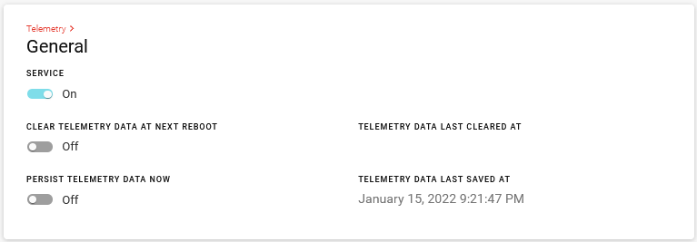
The following settings can be configured for AirLink OS Telemetry.
| SETTING | DESCRIPTION | OPTIONS | DEFAULT |
|---|---|---|---|
| SERVICE | Configure telemetry service to be enabled or disabled | On/Off | Off |
| CLEAR TELEMETRY DATA AT NEXT REBOOT | Erases all telemetry data at next reboot | Off/Pending | Off |
| PERSIST TELEMETRY DATA NOW | Saves telemetry data to flash storage. This is also automatically done at shutdown | Off/Pending | Off |
| TELEMETRY DATA LAST CLEARED AT | Shows the date and time that all telemetry data was last cleared. Read only. | N/A | N/A |
| TELEMETRY DATA LAST SAVED AT | Shows the date and time that all telemetry data was last saved. Read only. | N/A | N/A |
Telemetry Status
To view the status of your telemetry configuration, go to Status > Services > Telemetry.
This section provides some additional data regarding the CAN bus, such as the SAE Standard/Protocol in use, and the baud rate.
The data shown here will vary depending on your router model and which telemetry settings are enabled.
J1939 and J1979 protocols are currently supported. Semtech is investigating support for J1979-2 and J1979-3 and VDV 238 protocols. AirLink OS can currently detect both J1979 and J1979-2, but as shown below, Telemetry status will indicate whether a protocol version is not supported.

Custom Reports
Custom reports allow you to tailor your reports to better suit your needs. Initially you would define the report with specific data content and then you would assign it to the trigger event.
REPORTS
Define reports with your specific data requirements that can be sent to an MQTT broker.

| SETTING | DESCRIPTION |
|---|---|
| REPORT TITLE | Name of the report used to reference this report in the trigger definitions section. Report Title is not sent as part of the report. |
| REPORT MODE | Destination of where reports will be sent to. The MQTT configuration will only display when the REPORT MODE is set to the MQTT option. |
| MQTT TOPIC REPORT NAME | Name of the report that will be included in the MQTT TOPIC. |
| REPORT CONTENT | List of all telemetry data points that will be used to generate a report. It is possible to select more than one of these data points for each report. |
| GENERATE THIS REPORT AT POWER ON |
Report that will be generated when the device powers on. Note: Only one report can be selected. |
| GENERATE THIS REPORT AT POWER OFF |
Report that will be generated when the device powers off. Note: Only one report can be selected, and in situations where there is an abrupt power disconnect a report may not be generated. |
PERIODIC TRIGGERS (Generate reports at fixed intervals)
Reports can be generated at fixed time intervals using Periodic Triggers.

| SETTING | DESCRIPTION |
|---|---|
| ENABLE | When enabled, the configured report will be generated at each configured interval. Default is On. Options are On/Off. |
| GENERATE THIS REPORT… | List of reports that have been defined. Only one report can be selected. |
| EVERY… (SECONDS) | Number of seconds between each report interval |
UNCONDITIONAL TRIGGERS (Generate reports upon every data sample)
Reports can be generated when a data sample changes using Unconditional Triggers.

| SETTING | DESCRIPTION |
|---|---|
| ENABLE | When enabled, the configured report will be generated at each data sample. Default is On. Options are On/Off. |
| GENERATE THIS REPORT… | List of reports that have been defined. Only one report can be selected. |
| AT EVERY SAMPLE OF… |
When the data item sampled has changed from the last sample, the configured report will be generated. Options are:
|
Example 1: GPIO Input Cumulative
GPIO Input Cumulative is calculated using the Primary GPIO Input (line 4 of the power connector). Any change in the GPIO Input will affect the GPIO Input Cumulative and generate a report.
Example 2: WAN Ready
A WAN Ready sample is generated when WAN connectivity of the router switches between up or down.
Example 3: Ignition Status
- Time A: Ignition is DOWN.
- Time B: Ignition is UP.
- Time C: Ignition is DOWN.
Two Ignition Status samples are generated because the Ignition Status changed.
Example 4: Primary WAN
A PRIMARY WAN sample is generated whenever there is a switch in which interface is evaluated as primary.
- Time A: Wi-Fi Client is UP and is designated as the PRIMARY WAN. Cellular is also UP.
- Time B: Wi-Fi Client is UP. Cellular is DOWN.
No PRIMARY WAN sample is generated in this example.
- Time A: Wi-Fi Client is UP and is designated as the PRIMARY WAN. Cellular is also UP.
- Time B: Wi-Fi Client goes down. The PRIMARY WAN designation is re-evaluated to see if Wi-Fi Client is still the PRIMARY WAN, and it is not. Wi-Fi Client – Down. Cellular – New PRIMARY WAN.
A PRIMARY WAN sample is generated in this example.
DELTA TRIGGERS (Generate reports at minimum change in value or maximum elapsed time)
Reports can be generated using Delta Triggers when the sampled value has changed at least the configured amount since the last sample or a configured maximum time has passed.

| SETTING | DESCRIPTION |
|---|---|
| ENABLE | When enabled, the configured report will be generated when the sampled value has changed at least the configured amount since the last sample or a configured maximum time has passed. Default is On. Options are On/Off. |
| GENERATE THIS REPORT… | List of reports that have been defined. Only one report can be selected. |
| WHEN THIS ITEM’S SAMPLED VALUES… |
Options are:
|
| CHANGE BY THIS AMOUNT SINCE LAST REPORT… | Range from 0 to 1000000 |
| OR THIS TIME ELAPSES SINCE LAST REPORT (OPTIONAL - SECONDS)… | Range from 1 to 3000000 |
LEVEL TRIGGERS (Generate a report for each monitored data sample that meets the trigger condition)
Reports can be generated when a configured condition is true.

| SETTING | DESCRIPTION |
|---|---|
| ENABLE | When enabled, the configured report will be generated when the configured condition is true. Default is On. Options are On/Off. |
| GENERATE THIS REPORT… | List of reports that have been defined. Only one report can be selected. |
| WHILE THIS ITEM’S SAMPLED VALUES ARE… |
Options are:
|
| <RELATIONAL OPERATOR> |
Options are:
|
| THIS THRESHOLD VALUE | Range from -1000000 to 1000000 |
EDGE TRIGGERS (Generate one report when monitored condition becomes true)
A single report can be generated when a monitored condition crosses the configured edge threshold.

| SETTING | DESCRIPTION |
|---|---|
| ENABLE | When enabled, the configured report will be generated when the configured condition is true. Default is On. Options are On/Off. |
| GENERATE THIS REPORT… | List of reports that have been defined. Only one report can be selected. |
| WHEN THIS ITEM’S SAMPLED VALUES BECOMES |
Options are:
|
| <RELATIONAL OPERATOR> |
Options are:
|
| THIS THRESHOLD VALUE | Range from -1000000 to 1000000 |
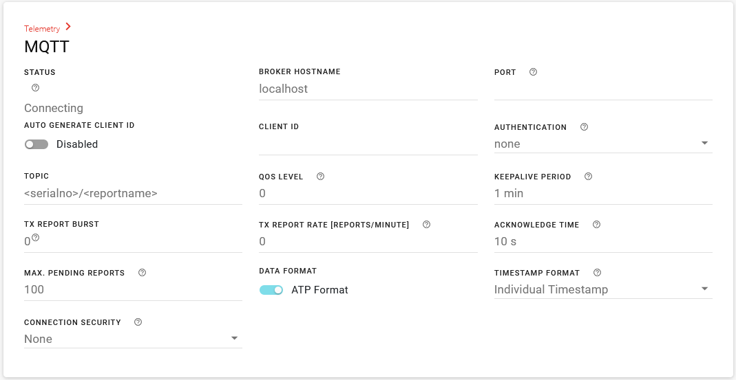
MQTT
The MQTT section appears only when a custom report has the REPORT MODE set to an MQTT option.
A destination MQTT broker can be configured using the following settings.
| SETTING | DESCRIPTION | OPTIONS | DEFAULT |
|---|---|---|---|
| BROKER HOSTNAME | Hostname of MQTT broker | IPV4 | localhost |
| PORT | Port that the MQTT broker is listening for incoming connections | Default port normally used is 1883. See your MQTT broker administrator. | N/A |
| AUTO GENERATE CLIENT ID | Enables the router’s serial number to be used as the client ID. Enable AUTO GENERATE CLIENT ID if your MQTT broker configuration rejects connections with an empty client ID. You can enable and add this setting to a template and apply it to your fleet instead of configuring a unique client ID for every router. | Enabled, Disabled | Disabled |
| CLIENT ID/ GENERATED CLIENT ID |
Enter a unique MQTT client ID for the router, if required by the MQTT broker. Leave blank for the MQTT broker to assign a client ID. When AUTO GENERATE CLIENT ID is enabled, the router serial number is displayed as the GENERATED CLIENT ID. |
N/A | N/A |
| AUTHENTICATION | Authentication information used to connect to MQTT broker |
|
None |
| TOPIC |
Used to identify the subject of a message.
6Q1099009902AC24/test {
  “atp.ser” :
   {
        “t”: 1693258321.3640001,
        “v” : “6Q1099009902AC24”
    },
        “ts” : 1693268920.464
}
|
<serialno>,<usbmac>,<ethernetmac>,<clientid>,<reportname>, or user defined. | <serialno>/<reportname> |
| QOS LEVEL | Quality of Service level |
|
0 |
| KEEPALIVE PERIOD | Maximum time that can elapse between two messages | 0 to 3600 s | 1 MIN |
| TX REPORT BURST | Maximum number of reports to send before rate limiting | 0 to 1000 | 0 |
| TX REPORT RATE [REPORTS/MINUTE] | Maximum number of reports to send per minute | 0 to 6000 | 0 |
| ACKNOWLEDGE TIME | Time to wait for acknowledgement | 1 to 600 s | 10 s |
| MAX PENDING REPORTS | Maximum number of pending reports before it will start to purge the oldest | 100 to 100000 | 100 |
| DATA FORMAT | Format of data sent to MQTT broker. |
|
ATP FORMAT |
| TIMESTAMP FORMAT | Format of timestamp used in report sent to MQTT broker. |
|
Individual Timestamp |
| CONNECTION SECURITY |
Sets how the security of the MQTT connection is handled. AirLink OS supports TLS encryption for MQTT traffic. |
|
None |
| ROOT CERTIFICATE |
When CONNECTION SECURITY is set to Use TLS with Custom CA, select or create a root certificate. For more information about certificates, see Managing Security Certificates. 
|
Any existing root certificate |
N/A |
More information about MQTT can be found here.