Configuring Power Settings
AirLink OS gives you options for managing router power usage, depending on your application and hardware configuration. The power management features enable you to configure the router for use in:
- mobile applications where the router draws power from the vehicle
- power-sensitive environments (such as solar-powered installations) where the router must use significantly less power than in locations where power is readily available.
 Initializing Table Of Contents...
About Standby Mode
Under System > Power Management > Standby Mode, you can configure the router to enter and exit standby mode (during which the router consumes minimal power) based on a low voltage threshold, the state of the ignition sense input, an I/O input, or configure it to operate only at certain times of day.

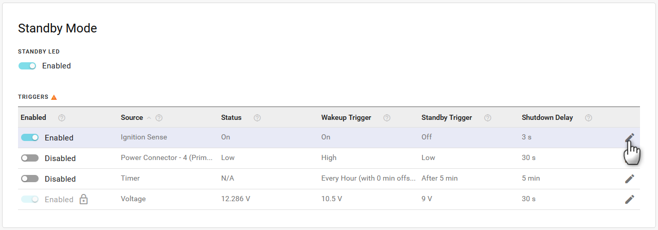
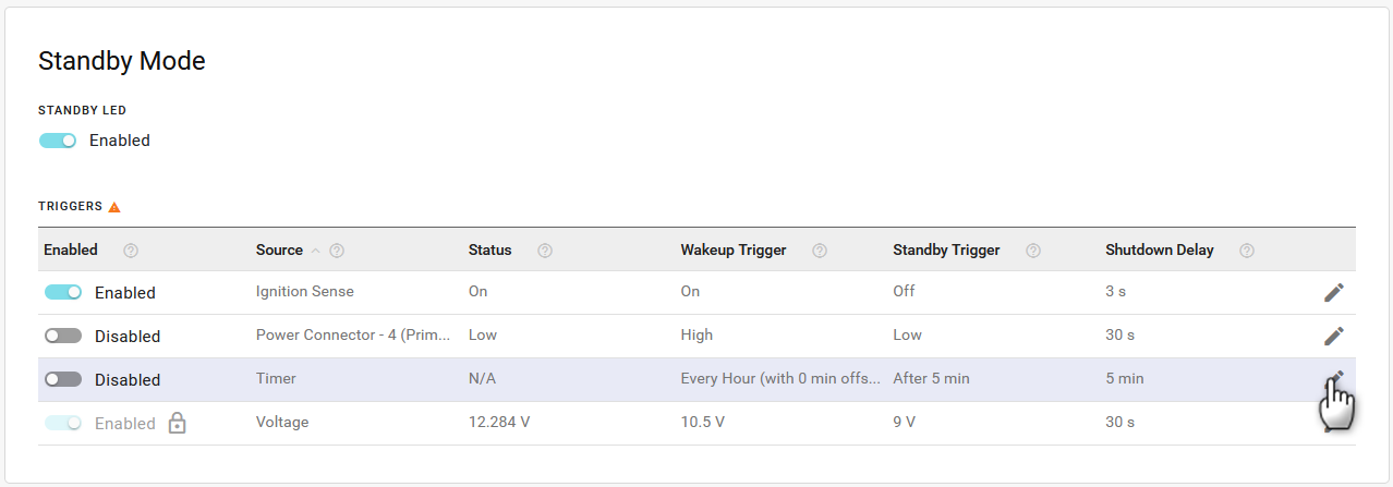
The Standby Mode section has the following settings:
The STANDBY LED setting enables or disables the Standby LED. When enabled (the default setting), the Power LED is solid red when the router is in standby mode. When disabled, the Power LED is off when the router is in standby mode, which reduces power draw.
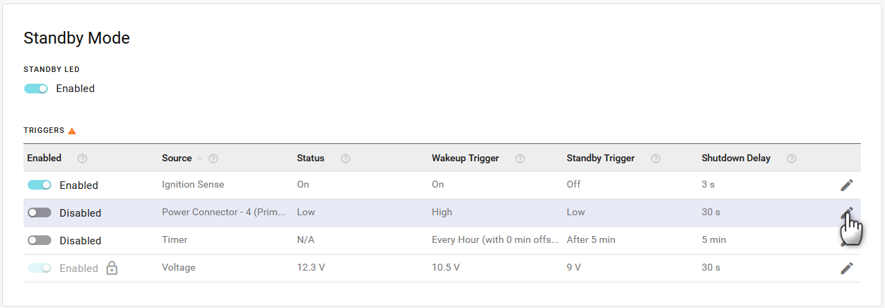
The TRIGGERS table lists the configurable trigger sources that control how the router enters and exits standby mode. You can enable or disable each trigger (except Voltage) from the table, or click Edit (
 ) to configure the trigger thresholds. The triggers are:
- Ignition Sense: For routers installed in vehicles, the Ignition Sense trigger can put the router into standby mode when the vehicle ignition is off and wake up the router when the ignition is on.
- Primary IO: Pin 4 on the router power connector is a GPIO line that you can configure to control standby mode. When connected to a switch or sensor, the GPIO can wake the router from standby mode to establish communication on demand.
- Timer: Configures the router to wake from standby mode at a regular interval for a defined duration. This setting is useful when the router is connected to a renewable power source. You can configure the router to wake up and report at a regular interval every day while conserving power at other times.
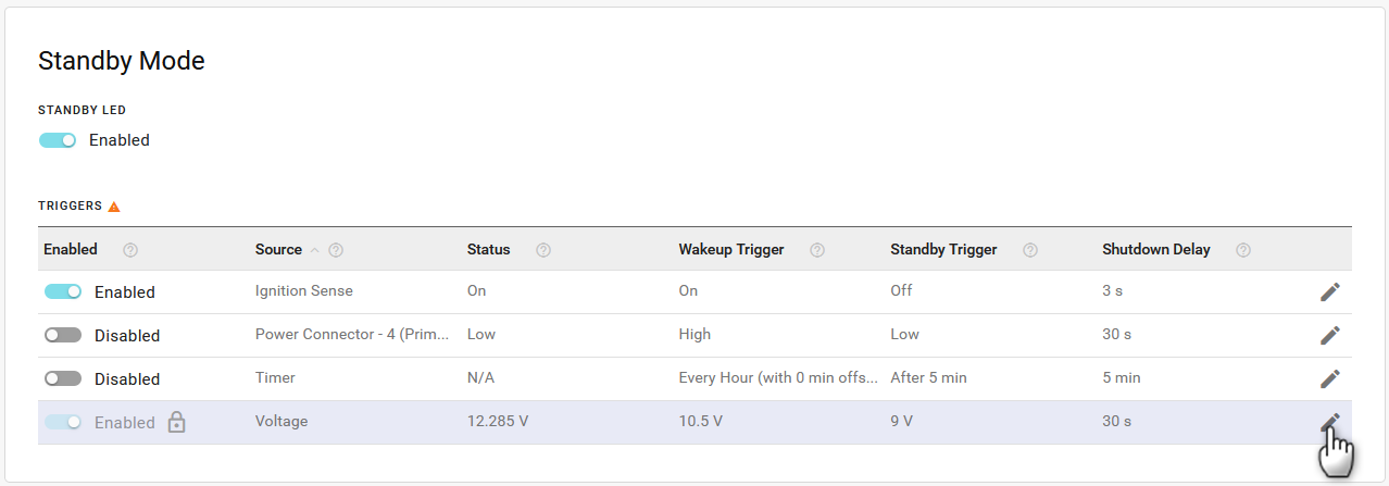
- Voltage: You can configure the router to enter and exit standby mode based on low/high input voltage thresholds.
 ) to configure the trigger thresholds. The triggers are:
For more information on standby mode power consumption, router installation and Ignition Sense and GPIO wiring, please refer to the AirLink RX400-EX400 Hardware User Guide .
Ignition Sense
To edit an Ignition Sense trigger:
- Click Edit (
) in the table on the row for Source > Ignition Sense.
- In Edit Source, enable or disable the Ignition trigger. Ignition is enabled by default.
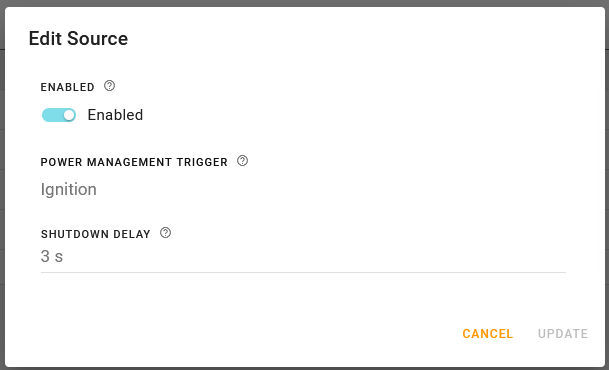
- Set the SHUTDOWN DELAY. The shutdown delay controls how soon the router enters standby mode after the vehicle ignition is turned off. For short vehicle stops, the delay can keep the router powered on while the vehicle is off.
- Range is 2–32767 seconds (default is 3)
- Click UPDATE.


Primary IO
To edit an I/O trigger:
- Click Edit (
) in the table on the row for Source > Power Connector 4 (Primary IO).
- In Edit Source, enable or disable the Primary IO trigger. The Primary IO trigger is disabled by default.
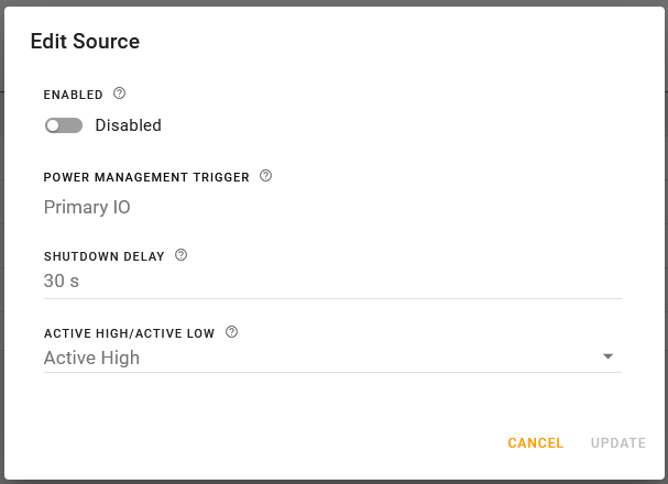
- Select the delay (in seconds) between the I/O state change and the router entering Standby mode. The delay can keep the router powered on during brief state changes in the Primary IO trigger.
- Range is 2–32767 seconds (default is 30)
- Set which logical state of the GPIO makes the router enter or exit standby mode. If set to Active High, the router wakes up and remains on while the GPIO is high and enters standby mode when the GPIO is low. If set to Active Low, the router wakes up and remains on while the GPIO is low and enters standby when the GPIO is high.
- Click UPDATE.


Timer
To edit a Timer trigger:
- Click Edit (
) in the table on the row for Source > Timer.
- In Edit Source, enable or disable the Timer trigger. The Timer trigger is disabled by default.
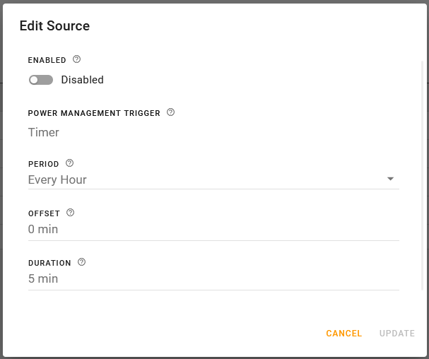
- Select a time PERIOD, which sets how often the router wakes up from standby mode.
- Range is Every Hour, Every 2 Hours, Every 3 Hours, Every 4 Hours, Every 6 Hours, Every 8 Hours, Every 12 Hours and Every Day (default is Every Hour)
- Select an OFFSET in minutes. This sets how long after the hour the router wakes up from standby mode.
- Range is 0–1440 minutes (default is 0)
- Select a DURATION. This sets how long the router operates before returning to standby mode.
- Range is 5–1440 minutes (default is 5)
- Click UPDATE.


Voltage
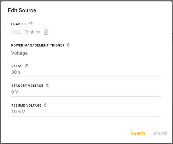
The Voltage trigger is enabled by default and cannot be disabled. You can configure custom values for low-voltage standby DELAY, STANDBY VOLTAGE and RESUME VOLTAGE.
To edit a Voltage trigger:
- Click Edit (
) in the table on the row for Source > Voltage.
- In Edit Source, set a DELAY, which is the time period (in seconds) that the voltage to the router must drop below the STANDBY VOLTAGE before the router goes into standby mode.
- Range is 30–3600 minutes (default is 30)
- Range is 30–3600 minutes (default is 30)
- Set the STANDBY VOLTAGE. If the incoming voltage to the router is below the STANDBY VOLTAGE for the DELAY period, the router goes into standby mode.
- Range is 5.8–29.5 V (default is 9)
- Set the RESUME VOLTAGE. This is the voltage at which the router exits standby mode and resumes normal operation.
- Range is 6.8–30 V (default is 10.5)
- Click UPDATE.


The RESUME VOLTAGE must be higher than STANDBY VOLTAGE by more than 0.5 V. For example, if you set the Resume Voltage to 12 V, the highest number you can set for the Standby Voltage is 11.4 V.
Exercise caution when setting the Voltage Thresholds. Before setting the RESUME VOLTAGE, ensure that you have a power source readily available that can supply the configured voltage. The reset button is not available when the router is in standby mode, so you cannot use it to reset the router to the factory default Standby Mode settings.