Configuring I/O
You can configure the router’s General Purpose Input/Output (GPIO) pins in AirLink OS. The pins can be used to turn switches on and off, or report data such as temperatures, pressures and flow rates.
The XR router has five I/O pins available for input/output configuration:
| HARDWARE PIN NUMBER | LOCATION | AIRLINK OS ID | CONFIGURABLE FUNCTIONS |
|---|---|---|---|
| 4 | Power Connector | Primary IO | Digital Input, Analog Input 1 |
| 7 | Auxiliary I/O | GPIO 2 | Digital Input, Analog Input |
| 6 | Auxiliary I/O | GPIO 3 | Digital Input, Analog Input |
| 3 | Auxiliary I/O | GPIO 4 | Digital Input |
| 2 | Auxiliary I/O | GPIO 5 | Digital Input |
1. The power connector GPIO (pin 4) digital input can also be used to put the device into a standby mode and to wake the router up.

For more information, refer to the Hardware Guide for the XR router.
 Initializing Table Of Contents...
Configuration
Go to System > I/O > Configuration to set the mode for each pin.

MODE: sets the function of the Auxilary I/O. The mode settings available are:
Digital Input
Analog Input
Disabled
Once the Mode is selected, a corresponding entry will appear in the below Analog Inputs table, and/or Digital Inputs table.
Analog Inputs
Analog inputs monitor a voltage range in small increments. This allows you to monitor equipment that reports status as an analog voltage. Examples include:
Power supply voltage
Temperature, weight, volume, flow represented as voltage
An incremental gauge with a voltage output
Vehicle battery voltage

The I/O Configuration screen enables you to transform the voltage readings to a more convenient unit of measurement. For example, degrees Celsius or Fahrenheit for temperature, liters for volume, etc.
DEADBAND: the minimum change in mV since last analog I/O value was received, that is needed to update the value again.
VALUE: raw analog value displayed in mV.
COEFFICIENT: a multiplicative value used in calculating the Transformed Value
OFFSET: a value used to compensate the Transformed Value
TRANSFORMED VALUE: calculated as (Value in units of Volts * Coefficient) + Offset. Allows for conversion of the analog I/O value to meaningful ranges/values where the Transformed Value can then be used in the chosen events reporting output.
The transformation function uses VALUE in units of volts, not millivolts, to display the TRANSFORMED VALUE.
Data sampling is taken over twenty measurements during a 250 ms interval. The measurements are averaged to generate a sample. If the sample has changed by the amount of the Deadband or a time period of 2.5 minutes has passed, then the Value is updated.
Step 1 - Coefficient and Offset
Before you configure, you need to locate or calculate the coefficient and the offset values.
Consult the user documentation for the equipment you want to monitor. It should provide you with the coefficient to convert volts to the appropriate unit of measurement and the offset value (the difference between the equivalent value for 0 volts and 0), or provide information on equivalent values for voltage readings from which you can calculate the coefficient and offset. (If this information is not available in the user documentation, contact the manufacturer.)
For example, if the equipment monitors temperature, and has a scale from 0 volts to 30 volts, the equipment specifications should provide information similar to the following:
0 V is equivalent to –20°C
30 V is equivalent to 100°C
This is expressed algebraically as follows:
a * 0V + b = –20C
a * 30V + b = 100C
where:
a = coefficient
b = offset
For this example, you can calculate a as follows:
(a * 30V + b) – (a * 0V + b) = 100C – (–20)
a * 30V = 120V
a = 4
To calculate b, substitute a into the first equation above:
4 * 0V + b = –20
b = –20
Step 2 - Configure AirLink OS
For each of the analog inputs you want to configure:
Go to System > I/O > Analog Inputs.
Enter the values for the coefficient and offset. (In this example, the coefficient is 4 and the offset is –20.)
AirLink OS will show the value of the transformed analog input.
Digital Inputs
Digital inputs monitor contact closures on a switch. This allows you to monitor changes such as:
When a door or latch is open or closed
When a container is full or empty
When a switch or valve is opened or closed
The level of fuel in a vehicle (connected to an on/off sensor)
When the trunk of a vehicle is opened or closed
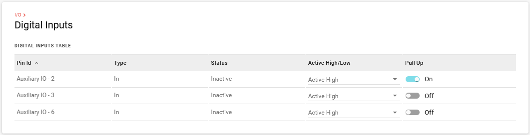
TYPE: options are Disabled and In (input)
STATUS: options are Inactive (false), Active (true)
ACTIVE HIGH/LOW: options are Active High, Active Low
PULL UP: options are On or Off

Configure Digital Input
For each of the digital inputs you want to configure:
In AirLink OS, go to System > I/O > Digital Inputs.
Select Active High or Active Low.
Enable/disable the Pull Up.
The power connector GPIO (pin 4) digital input can also be used to put the device into a standby mode and to wake the router up. To configure this, see Configuring Power Settings (MCU) .
GPIO Reporting
If you want to add GPIO state to reports, you can do so in a custom report. See Services > Telemetry > Custom Reports.